8200-M585-O1 Rev D 210 Installation & Technical 14
INSTALLATION, CONT.
Optically Isolated Remote Inputs
Included with the I/O are 4 programmable inputs that may be used to remotely (up to 100 feet)
initiate various functions within the indicator. These inputs are accessed via a terminal block
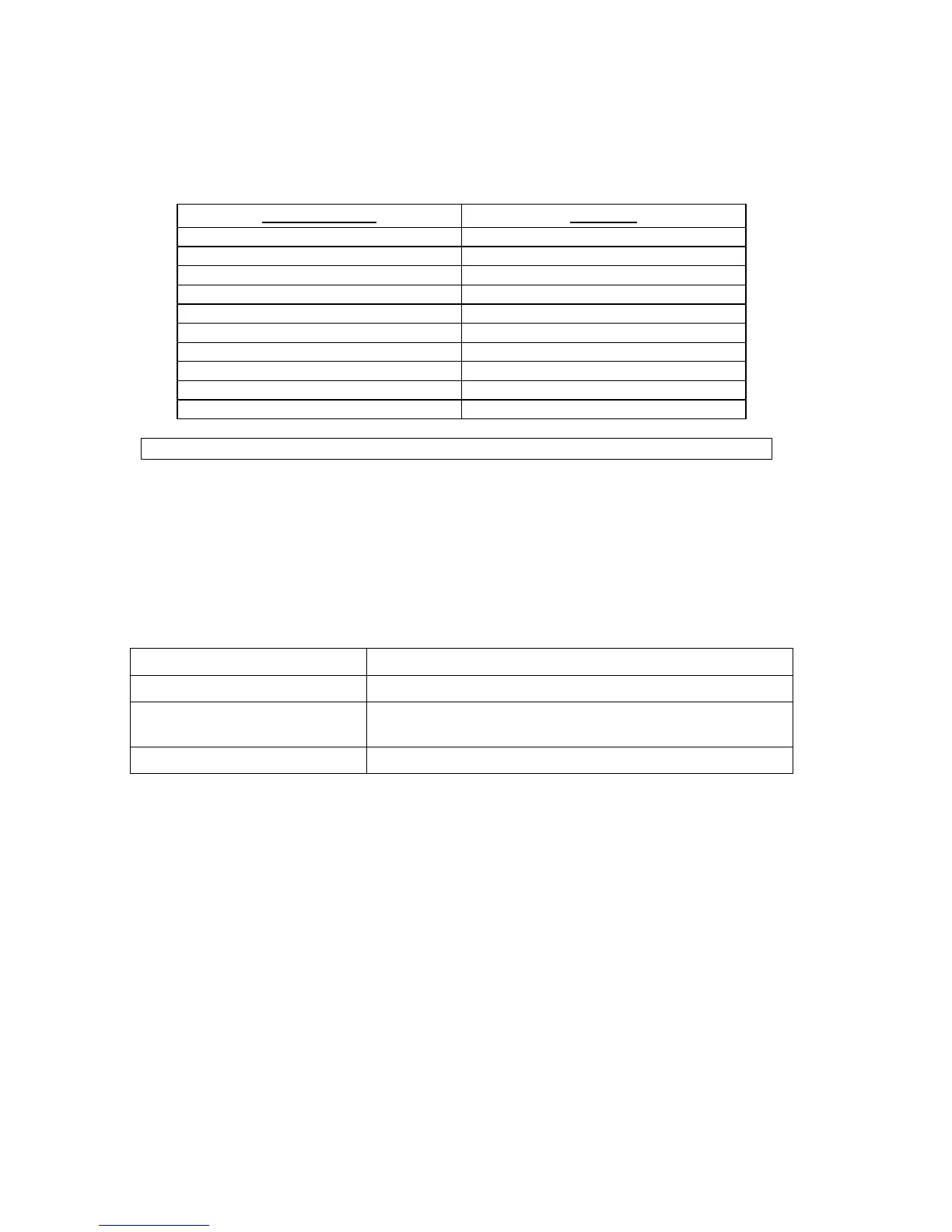
(P3) on the back of the PC board (see Figure No. 15). The 8 inputs are defined as follows:
TERMINAL NO.
Function
1 SRC 12-24VDC
2 Gross
3 Print
4 Zero
5 Tare
6 *
7 UNITS
8 START
9 STOP
10 GND
NOTE: The input must be momentarily connected to GND to initiate the function.
AC Input Relay Board(s)
The AC Input Relay Board(s) are mounted in an external junction box for use with the 210
Indicator. The RB4-ACIN (115 VAC) or RB4-ACINV (230 VAC) contain one board and
supports 4 inputs (jumper selectable). The RB8-ACIN (115 VAC) or RB8-ACINV (230 VAC)
contain two boards and supports eight inputs that are jumper selectable. The relay board used
in the 115 VAC versions is Cardinal p/n 8200-C324-0A. The 230 VAC version uses relay
board Cardinal p/n 8200-C324-1A. Connect the devices as shown in Figure No. 10.
INPUT RELAY TYPE IAC-5 90 to 140 VAC @ 6mA maximum for each plug-in relay
INPUT RELAY TYPE IAC-5A 180 to 280 VAC @ 6mA maximum for each plug-in relay
OUTPUT 5VDC @ 12mA from the 210 main pc board assembly P3
12VDC @ 12mA maximum from external source
CONNECTION Removable plug-in screw terminals for up to 14 AWG wire

 Loading...


