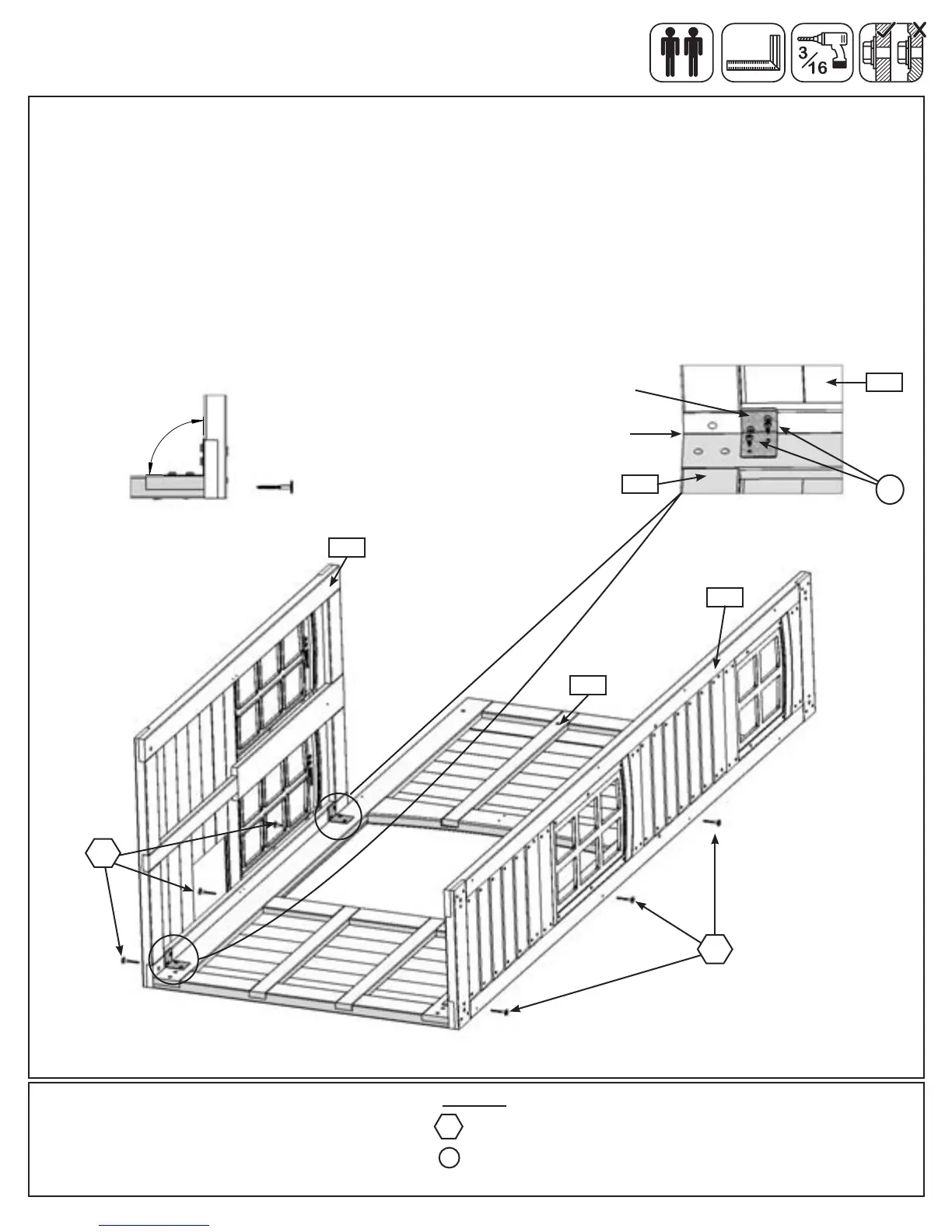
Step 5: Swing Side Panel Assembly
Part 4
Hardware
6 x 1/4 x 2-1/2” Wafer Lag
WL5
G: With a helper hold (051) SL Side Window Panel up against the left side edge of (043) SW Side Panel so the
bottom edges are ush. Attach both Corner Panel Brackets to (043) SW Side Panel with 2 (S8) #12 x 3/4” Pan
Screws per bracket. (g. 5.8 and 5.9)
Note: Make sure panels are square and ush to each other. (g. 5.10)
H: Pre-drill with a 3/16” drill bit, then fasten the (050) Narrow Window Panel and (051) SL Side Window Panel to
(043) SW Side Panel with 3 (WL5) 1/4 x 2-1/2” Wafer Lags per panel. (g. 5.8)
9
0
°
Fig. 5.10
051
Fig. 5.9
Fig. 5.8
Flush
WL5
WL5
S8
043
050
043
051
Corner Panel Bracket
4 x #12 x 3/4” Pan Screw
S8
36 support@cedarsummitplay.com