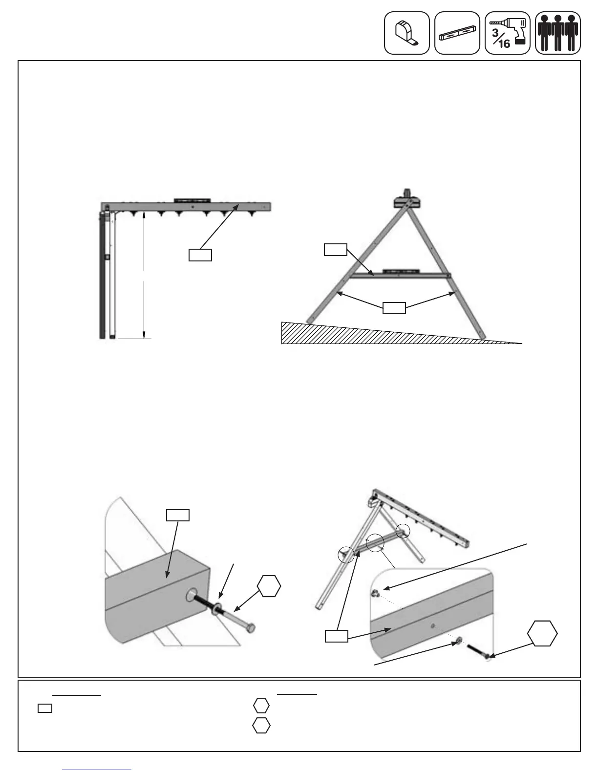
Step 28: Attach Cross Support
Hardware
Wood Parts
Pre-drill all holes using a 3/16” drill bit before installing the lag screws.
A: Check to make sure the (260) Engineered SW Beam is level and the bottom of the beam to the ground
measures 85”. (g. 28.1)
B: To adjust for uneven ground, raise or lower the (280) Support Cross on the (272) SW Post. Make sure the
Support Cross is level prior to attaching with the lag screws. (g. 28.2)
Fig. 38.1
2 x 5/16 x 4-3/4” Lag Screw
(5/16”atwasher)
1 x 5/16 x 2-3/8” Wafer Bolt
(5/16”atwasher,5/16”t-nut)
WB8
LS9
1 x Support Cross FSC 2-1/2 x 3 x 64”
280
360
C: Place (280) Support Cross between (272) SW Post at the previously determined spot and fasten with 1
(LS9) 5/16 x 4-3/4” Lag Screw (with at washer) per side. (g. 28.3 and 28.4) Notice one side is fastened on
the outside and one on the inside. It is important that each side is positioned exactly the same as the
diagram.(g.28.3)Tightenthelagscrewwhenyouaresure(280)SupportCrossislevel.
D: Attach 1 (WB8) 5/16 x 2-3/8” Wafer Bolt (with at washer and t-nut) to (280) Support Cross through the
middle hole. (g. 28.3) IMPORTANT! MAKE SURE THE BOLT IS ATTACHED TO MINIMIZE CHECKING OF
WOOD.
85"
5/16” T-Nut
Fig. 28.1
280
Fig. 28.2
Fig. 28.4
Fig. 28.3
5/16” Flat
Washer
5/16” Flat
Washer
LS9
280
260
280
272
WB8
97 support@cedarsummitplay.com