Fig. 9.10
Hardware
Wood Parts
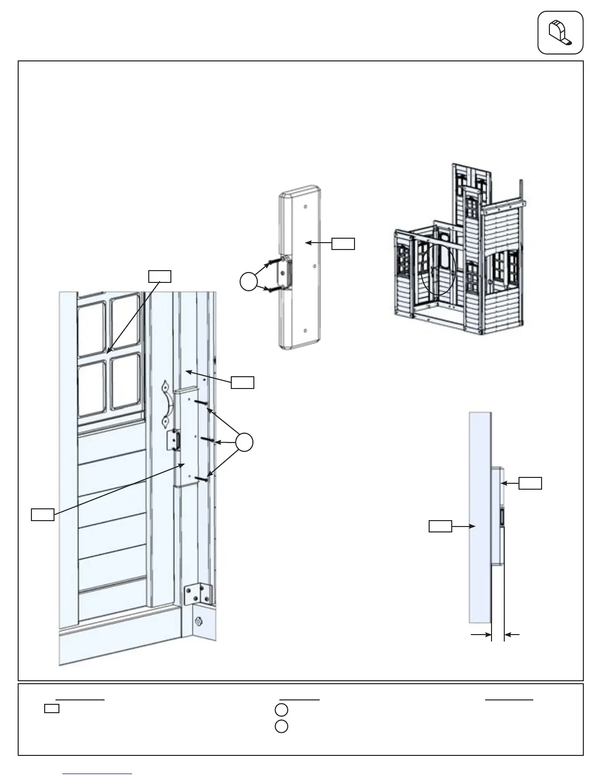
Step 9: Door Wall Assembly
Part 4
F: In the notched out opening of (091) Door Stop attach the Magnetic Catch using 2 (S18) #6 x 1” Wood Screws.
(g. 9.8) Important: Use a hand held screw driver and DO NOT over tighten.
G: On the inside of the assembly, attach (091) Door Stop to (061) Door Wall Window Panel with 3 (S15) #8 x
1-3/4” Wood Screws, making sure (091) Door Stop overhangs (061) Door Wall Window Panel by 1-1/4” and is in
position to receive the Catch Plate. (g. 9.9, 9.10 and 9.11).
Fig. 9.9
Fig. 9.11
Fig. 9.8
1 x Door Stop FSC 5/4 x 4 x 10”
091
2 x #6 x 1” Wood Screw
S18
3 x #8 x 1-3/4” Wood Screw
S15
061
Other Parts
1 x Magnetic Catch
091
S15
S18
091
090
061
091
1-1/4”
52 support@cedarsummitplay.com