061
Fig. 9.7
Hardware
Step 9: Door Wall Assembly
Part 3
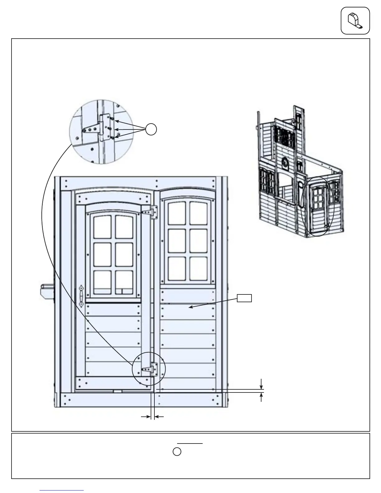
E: In the opening for the door, measure 5/8” from the top of Door Wall Window Panel bottom and maximum 5/8”
from right side of the opening which would be the Door Hinge side and attach the remaining side of the hinges to
(061) Door Wall Window Panel using 3 (S13) #6 x 5/8” Pan Screws per hinge. (g. 9.5, 9.6 and 9.7)
Fig. 9.6
Fig. 9.5
6 x #6 x 5/8” Pan Screw
S13
5/8”
S13
5/8”
51 support@cedarsummitplay.com