Fig. 9.3
Fig. 9.4
090
S13
S13
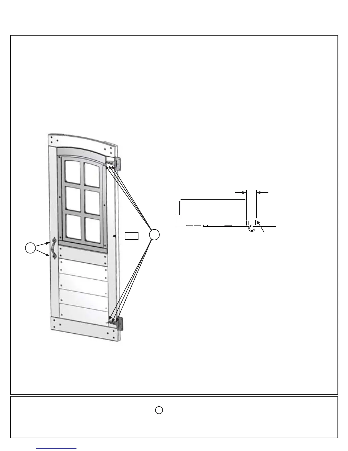
Outside View
1/2”
Hinge Stop
Hardware
Step 9: Door Wall Assembly
Part 2
C: On the outside of the (090) Door Window Panel attach the second Door Handle at approximately the same
place as the one on the inside. Use 2 (S13) #6 x 5/8” Pan Screws. (g.9.3)
D: Attach 2 Door Hinges on the outside of the (090) Door Window Panel on the opposite side from the Door
Handle. Judge spacing based on g. 9.3. Use 3 (S13) # 6 x 5/8” Pan Screws per Hinge.
Note: Hinge stops must be tight to (090) Door Window Panel. (g. 9.4)
8 x #6 x 5/8” Pan Screw
S13
Other Parts
1 x Door Handle
2 x Door Hinge
Top View
50 support@cedarsummitplay.com