Emotron VS Series Quick Start Guide
- 35 -
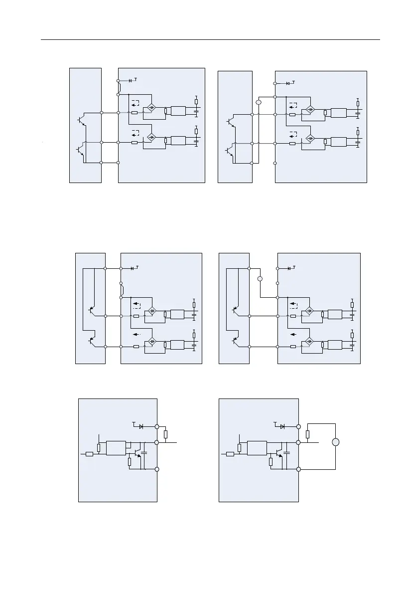
◆B: Open collector NPN connection
External
controller
7
1
+5
V
Inverter
GND
+
-
+5
V
GND
+
-
COM
DI1
DI7/HI
24
V
+24V
PLC
Jumper
Optocoupler
Optocoupler
External
controller
7
1
+5
V
Inverter
GND
+
-
+5
V
GND
+
-
COM
DI1
DI7/HI
24
V
+24V
PLC
+
-
20~30V
Optocoupler
Optocoupler
(a) Internal power supply (b)External power supply
Fig.3-23 External power supply open collector NPN connection
ATTENTION:
When external power supply is utilized, the jumper between +24V and PLC must be removed.
The voltage range of external power supply should be DC20~30V, otherwise normal operation could
not be assured and/or hazard of equipment damage exists.
◆C: Open collector PNP connection
External
controller
7
1
+5
V
Inverter
GND
+
-
+5
V
GND
+
-
COM
DI1
DI7/HI
24
V
+24V
PLC
Jumper
Optocoupler
Optocoupler
External
controller
7
1
+5
V
Inverter
GND
+
-
+5
V
GND
+
-
COM
DI1
DI7/HI
24
V
+24V
PLC
Jumper
+
-
20~30V
Optocoupler
Optocoupler
(a) Internal power supply (b)External power supply
Fig 3-24 internal power supply open collector PNP connection
3)Instructions of digital output terminal
+5V
24V
+24V
Y1,2
COM
Pull-up
resistor
Inverter
Optocoupler
+5V
24V
+24V
Y1,2
COM
Pull-up
resistor
Inverter
+
-
≤30V
Optocoupler
(a) Internal power supply (b)External power supply
Fig 3-25 wiring when Y2 and HO output with pull-up resistors
ATTENTION:
When set to be pulse output, Y2/HO terminal shall output 0~100kHz pulse signal.