Emotron VS Series Quick Start Guide
- 34 -
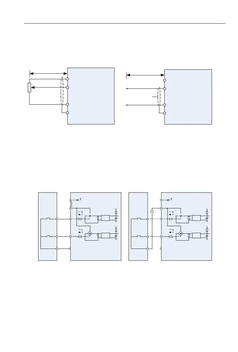
Description of Wiring of Signal Terminals:
1)Description Use the analog input terminal
Weak analog voltage signals are easy to suffer external interference, and therefore the shielded
cable must be used and the cable length must be less than 20 m, as shown in following figure. When
the analog input signal to an external power supply,AI1 Terminal wiring as shown in Fig 3-12
(a).When the input analog voltage signal is potentiometer,AI1 Terminal wiring as shown in Fig 3-12
(b) AI2/AI3 Similar to AI1.
+10V
AI1
GND
PE
1kΩ~5kΩ
DC 0~10V
<20m
Inverter
+10V
AI1
GND
PE
<20m
Inverter
DC 0~10V
(a) (b)
Fig 3-21 Analog input terminal wiring diagram
2)Instructions of Digital Input/output Terminals
Digital input & output signals cables should be as short as possible, shielded, and their shielded
layers should be properly grounded close to the side of drive. The cables should not exceed 20m.
When active drive is selected, take necessary filtering measures against power crosstalk, for
which dry contact control is recommended.
Control cables shall be kept no less than 20cm away from main circuit and strong current lines
(e.g. power lines, motor lines, relay lines and contactor lines) and should not be arranged in parallel
with strong current lines. In case it is inevitable to intersect strong current line, vertical wiring is
recommended to avoid drive faults as a result of noise. Operating instructions for switching value input
terminal
◆A: Dry contact
+5
V
Inverter
GND
+
-
+5
V
GND
+
-
External
controller
1
7
COM
DI1
DI7/HI
24
V
+24V
PLC
Jumper
Optocoupler
Optocoupler
+5
V
Inverter
GND
+
-
+5
V
GND
+
-
External
controller
1
7
COM
DI1
DI7/HI
24
V
+24V
PLC
+
-
20~30V
Optocoupler
Optocoupler
(a) Internal power supply (b)External power supply
Fig 3-22 Dry contact
ATTENTION:
When external power supply is used, the jumper between +24V and PLC must be removed.
Otherwise, it may result in equipment damage.
The voltage range of external power supply should be DC20~30V. Otherwise, normal operation
could not be assured and/or result in equipment damage.