CHLORIDE ACTIVE Interface description
945040.066 V02OCT/01 GB - 33
G
B
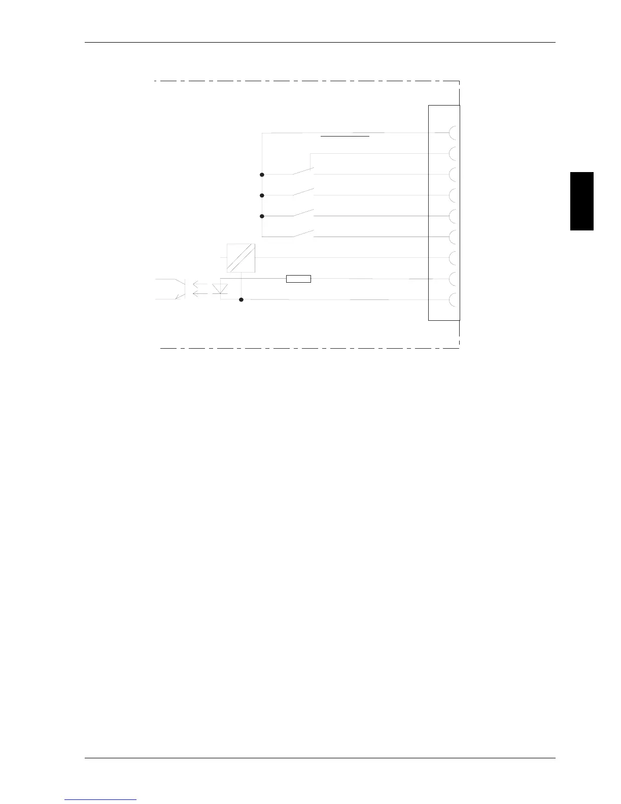
Fig. 18: COM 1 interface
INV SHUTDOWN
This input (pin 6: high signal +5 V … +12 V, t 1 s, pin 7: 0 V) makes it pos-
sible for the control computer to switch off the UPS in the event of a mains
failure. Upon mains restoration, the UPS starts independent of this signal
state.
AC FAIL
(N.O. between pins 2 and 4, N.C. between pins 3 and 4)
This signal is active when the mains voltage at the UPS input is not present
for at least 10 seconds or the mains voltage exits the tolerance range. The
signal is cancelled 850 ms following mains restoration.
BATT LOW
(N.O. between 5 and 4)
This output is active when the battery can continue to supply current at the
nominal load for only approx. 3 minutes.
=
=
4
3
2
5
1
8
9
6
7
COM M ON
AC FAIL
AC FAIL
BATT LOW
BYPASS ACTIVE
SUM ALARM
INV SHUTDOWN
12V
GND
COM 1