Overview of Screens Chore-Tronics® 2 Control
24
MT1843B
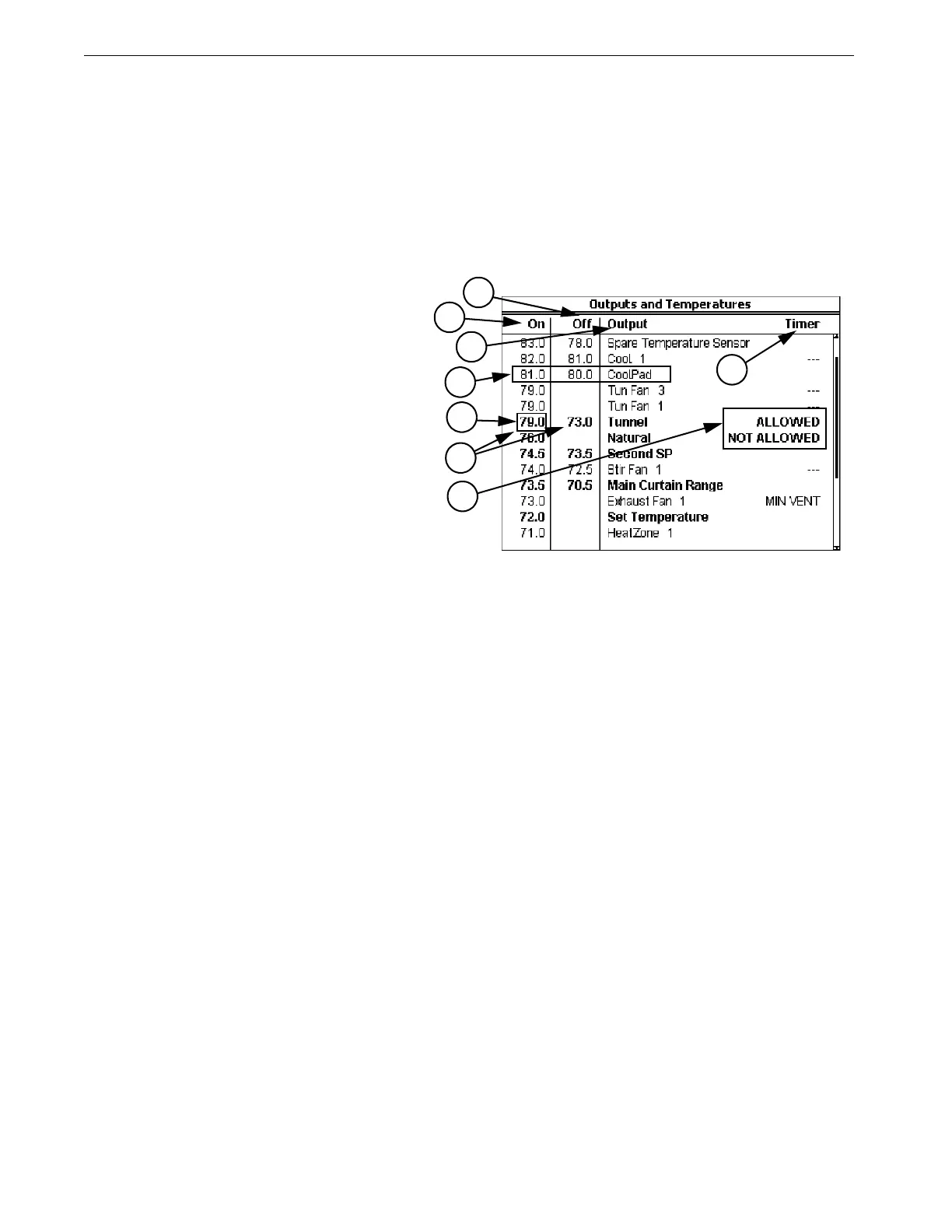
Screen 4: Outputs-Temperatures
Screen 4, (Figure 21) is a very important screen. It is the screen that determines at
what temperatures Outputs operate.
An important tip regarding the use of this screen is to get in the habit of asking
yourself which Temperature Sensor (or combination of Temperature Sensors) is
assigned to the various Outputs shown on this screen. For instance, in Figure 21
below, Exh Fans 3 and 4 are set to come “on” and “off” at the same temperatures,
they may not go “on” and “off” together if they are assigned to different Sensors in
screen 13.
3. The Output names listed in column 3 are a result of what is programed into screen 13.
4. In column 4 you attach a Timer to those Outputs you want to be affected by a Timer. See the screen 3
description regarding how the various Timers behave and which Outputs can have which Timers
attached to them.
5. This is the temperature of the Power Mode Sensor(s) where the Control will change from the Power
Mode to the Natural Mode.
6. The “on” and “off” temperatures of the Tunnel Mode are entered here. The Control will convert to the
Tunnel Mode when the Natural (if used) or Power Mode Sensor(s) raises to the Tunnel “on” tempera-
ture. The Control will convert back to the Natural (if used) or Power Mode when the Tunnel Mode Sen-
sor(s) reaches the “off” temperature. The minimum allowed difference between the Tunnel “on” and
“off” temperature is 3 degrees F.
7. The Cool Pad Range’s “on” and “off” temperatures have a very different meaning from the “on” and
“off” temperatures of the other Outputs. The “on” temperature is the high limit of the desired range
while the "off” temperature is the low limit of the desired range. See the "Cool Pad Function" section of
this Manual for more details regarding the COOL PAD function.
8. For both the Natural and Tunnel Modes it is possible to ALLOW or NOT ALLOW the mode to occur
in these fields of screen 4. Do not use the YES/NO questions in screen12 to temporarily disable either
mode.
MT1842-009 10/04
Figure 21. Screen 4: Outputs Temperatures
1
2
3
4
5
7
8
1. This column lists the “on” temperatures
of the outputs listed in column 3. For
outputs above the set temperature, the
output goes from “off” to “on” with ris-
ing temperature. For the Heat Zone Out-
puts, below the set temperature, they go
from “off” to “on” with falling tempera-
ture. After changing any temperatures in
the “on” column, the screen will re-sort
itself according to the “on” temperatures
the next time you select this screen.
2. This column lists the “off” temperatures
of the outputs listed in column 3. All
Heat Zone output’s “off” temperatures
(as the temperature rises) are fixed to be
0.5 degrees above their “on” tempera-
tures or the value specified in the OFF
column for that Ht. Zone. The “on-off
differentials’’ of all other outputs are
adjustable. For Fan outputs the “off”
temperatures are either the value of the
next lower Fan’s “on” temperature or
the value you specify in the OFF col-
umn for that output. The default “off”
temperature for the lowest temperature
Fan output is the set temperature if an
"off" temperature is not entered. The
minimum “on-off differential” allowed
6