Introduction to the Control Chore-Tronics® 2 Control
14
MT1843B
Relay Box Indication Lights and Auto/Manual Switches
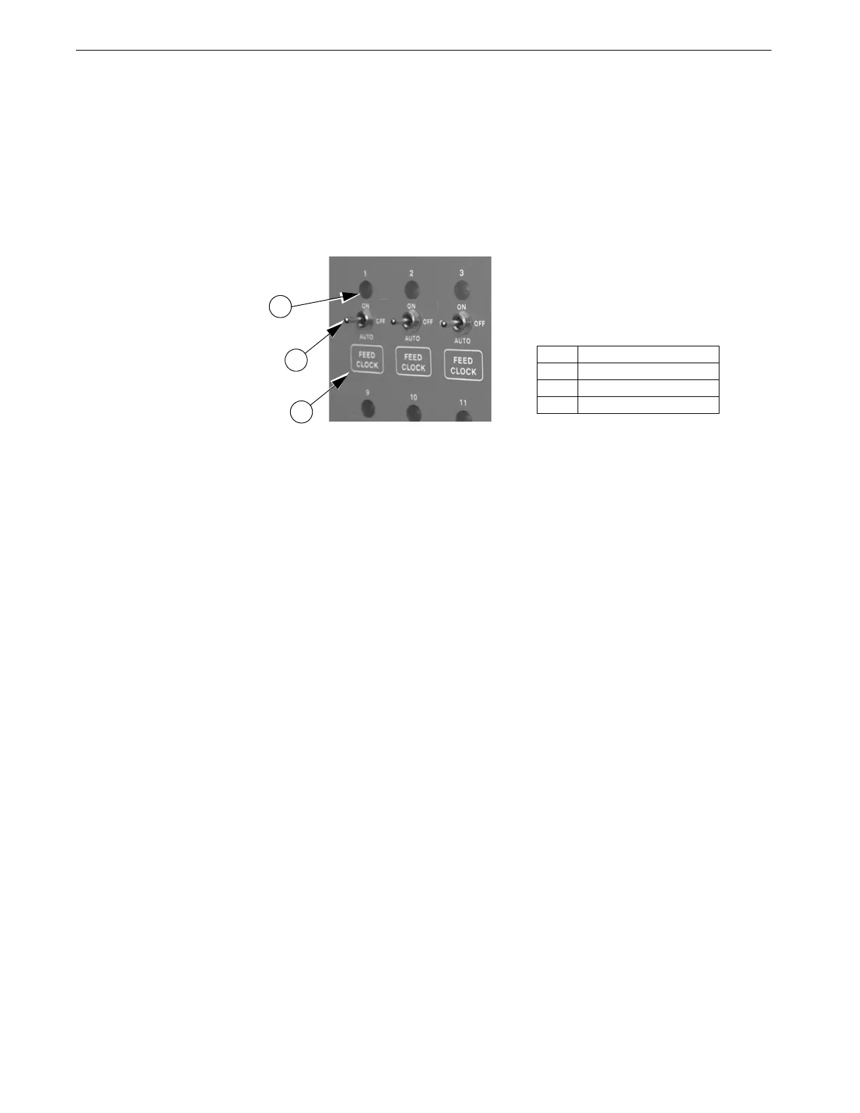
Each Relay Output has its own three position switch that allows the user to select
manual, off or automatic control of each Relay. The Relays and their corresponding
Switches are located in a separate box. Decals are supplied to label each Switch for
the Output function that is assigned to that Switch. The Switches can be placed in
three positions - "on", "off", or "auto". The "auto" position is for normal automatic
operation. Changing a Switch to "on" or "off" overrides "auto" operations. When a
switch that is assigned is placed in a position other than "auto", a message will appear
in the Current Conditions screen advising you to "Check Switches". The light above
each Switch indicates that the Switch's Relay is activated.
Figure 16. Indication Lights and Switches
Item Description
1 Indication Light
2Switch
3Decal
3
2
1