Chore-Tronics® 2 Control Control Installation
MT1843B
83
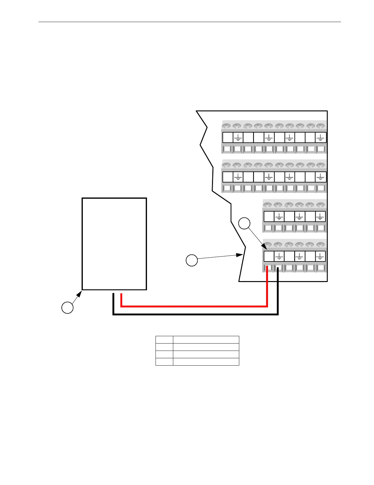
Remote Light Dimmer Control Wiring
Before connecting the I/O board to a Light Dimmer, be sure to check that the light
dimmer is equipped for remote control dimming. The Light Dimmer must be able to
accept a 0-10 or 10-0 Vdc signal from the I/O board. Refer to the information
provided by the Light Dimmer manufacturer for remote dimming wiring instructions.
The Light Dimmer connects to the I/O board at the analog output #1 (AO1) (See
Figure 97 below). Be sure that the positive terminal on the I/O board matches with
the positive wire/terminal on the Light Dimmer.5
Light Dimmer
0-10 Vdc Input
DI5
12V
DI7
12V
DI6
DI8
DI1
12V
DI3
12V
DI2
DI4
AO4
AO5 AO6
AO1
AO2 AO3
MT1842-171 01/05
Figure 97. Remote Light Dimmer Control Wiring
Item Description
1I/O Board
2 Light Dimmer
3 Analog Output #1
2
1
+
-
+
-
3