Overview of Screens Chore-Tronics® 2 Control
46
MT1843B
Setup Screens (Screens 13 & 14) and Initial Setup
The setup screens (Screens 13 and 14) is where the Control is told what it is
controlling. The Control is told which relays to control based on which sensors (if the
Output is controlled by temperature). The Control is also told which ventilation
mode(s) the Output relays are allowed to operate. Many of the settings that are
entered into these screens determine what will appear in several other screens.
Once the Control has been properly installed and all Outputs have been tested
manually, the Control is now ready to be set up. The following sections should be
used only as a guide to setting up the Control. These sections will provide a general
overview and procedure for programming and setting up the Control.
Before beginning to set up the Control, make sure that all of the toggle switches in
the relay box (es) have been placed in the manual "off" position. This will insure that
no Outputs will accidentally turn on during setup. Also make sure that the Output
stickers have been placed over the correct toggle switch and that the Input assignment
decal has been filled in properly. This will aid in programming the Control.
When first powering up and setting up the Control, the light next to the alarms button
(button #8) may flash red or green. Ignore this flashing light until the Control is fully
set up.
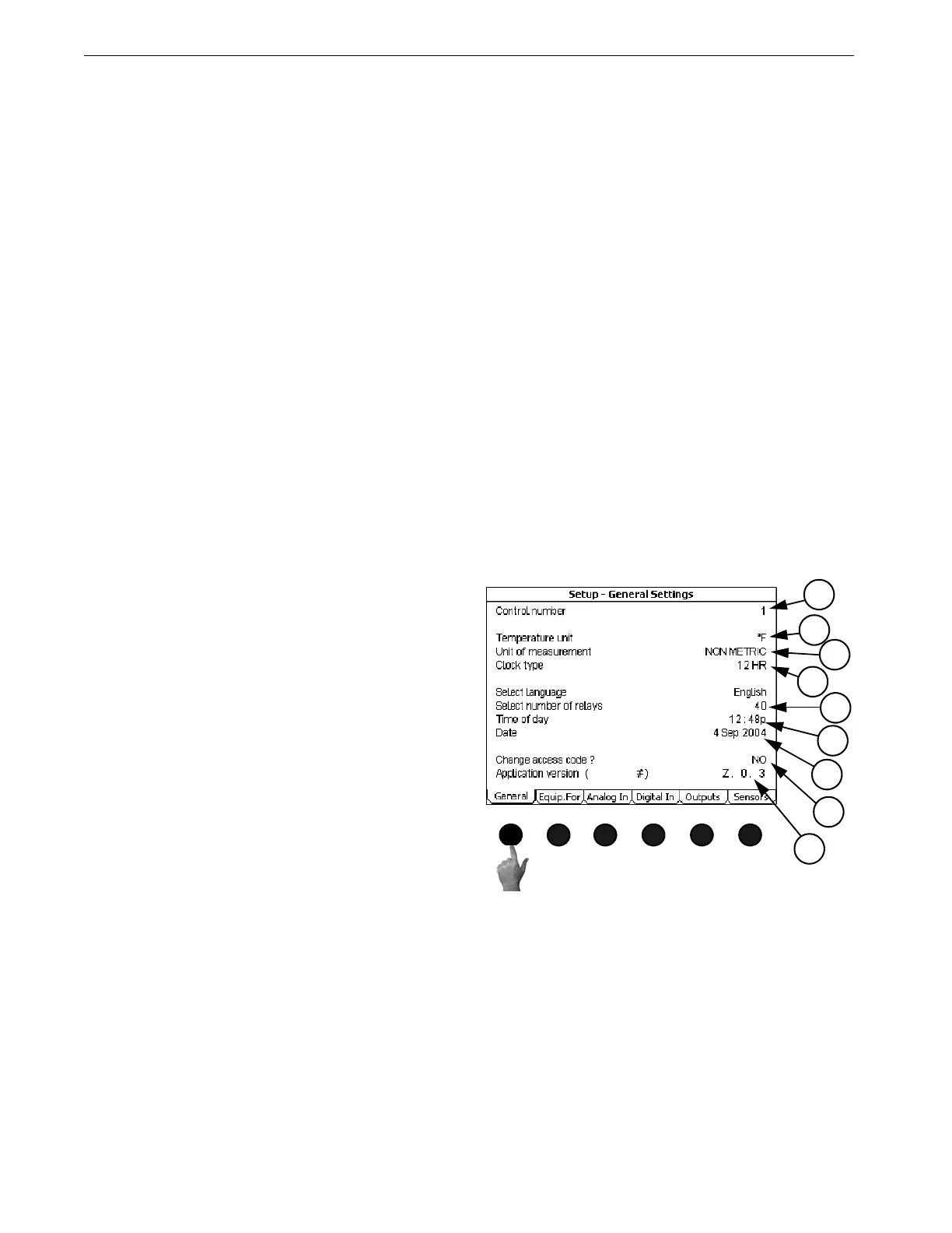
Screen 13: Setup-General
(Setup-General Screen) General Tab
Go to the Setup-General "General Screen" (Screen 13), by pushing Subject button 13.
1. Control number- Enter the Control's Control
number here. The Control number should
match the house number. This is especially
important if C-Central is being used.
2. Temperature unit- Select which temperature
unit (Fahrenheit or Celsius) the Control will
display the temperature sensor readings.
3. Units of measurement- Select which unit of
measurement (non-metric or metric) the
Control will use for measurements such as
water, feed and curtain measurements.
4. Clock Type-Select which clock type (12H or
24H) the Control will use to display the time
of day and to use in the Clocks (Screen 5)
screen.
5. Time of Day-Enter the current time of day.
6. Number of relays- Select the number of Out-
put relays (32-80 in multiples of 8) that are
currently connected to the Control.
7. Date-Enter the current Date
8. Change access code- The Control comes set from the factory with no access code required to make
changes. If an access code is desired first change the "NO" to a "YES" at the change access code line.
The Control will then ask for the old password. From the factory the old password is 1111. This is
entered by pushing the number 1 on the numeric keypad 4 times and pressing enter. Next enter a new
access code by using the numeric keypad and press enter. The Control will then ask for confirmation
of the new access code. Once an access code has been entered, the Control will ask for that code any
time the control has set idle (no buttons pressed) for more than 5 minutes, and the edit button is
pushed. If an access code is no longer desired, change the access code back to the factory setting of
1111, and no code will be required to make changes.
9. Application version and Serial number- The current application code version and the current serial
number of the Control.
Special Note:
MT1842-038 10/04
2
3
1
4
6
5
7
8
9
Figure 59. Setup-General Screen: General Tab