Chore-Tronics® 2 Control Control Installation
MT1843B
67
Mounting the Control
32 and 40 Output Control Mounting
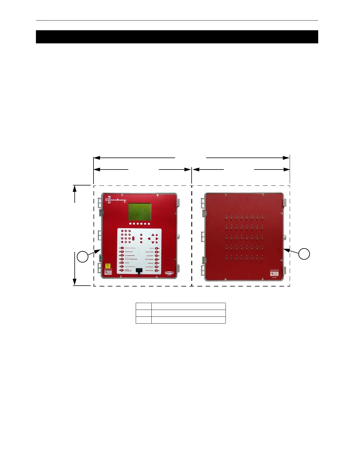
A 32 or 40 Output Chore-Tronics
®
2 Control consists of a Main Box and a Relay
Box. The Main Box and the Relay box each requires a minimum mounting area of
21 in. [53 cm] x 21 in. [53 cm] (See Figure 73).This dimension allows extra room
for the control doors to open. The boxes should be mounted level and square on a
solid backing using the mounting holes provided.
When mounting the Main Box and the Relay Box, make sure the two boxes are as
close together as possible to reduce the likely hood of a communication failure. Make
sure that the Relay Box is mounted so that the relay indicator lights are visible when
standing at the Main Box.
Control Installation
Note:
21" Min. 21" Min.
42" Min.
21" [53cm] Min.
Figure 73. 32 and 40 Output Control Mounting
Item Description
1 Main Box
2 Relay Box
3
3