Wiring Diagrams Chore-Tronics® 2 Control
104
MT1843B
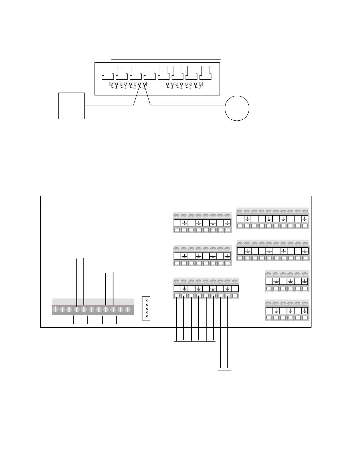
Turbo-Cool™ Wiring
I/O Board Wiring
Mt1701-Turbocoolwiring 10/01
SITUATION WHERE THE TURBO COOL PUMP HAS BEEN ASSIGNED TO RELAY 4 IN THE SETUP SCREEN.
T.COOL
PUMP
EACH RELAY'S CONTACTS ARE CLOSED WHEN THE OUTPUT THAT IS ASSIGNED TO THAT
ALL OUTPUT RELAYS ARE SPST WITH DRY CONTACTS AS SHOWN. THIS SHOWS A TYPICAL
NOTE:
CIRCUIT
L1
T. COOL
FOR
BREAKER
L2
RELAY IS SUPPOSED TO BE ON.
#1 #3 #2 #4 #5 #6 #8 #7
TYPICAL WIRING OF OUTPUT RELAYS
#3 #1 #2 #4 #5 #6 #7 #8
Figure 113. Turbo-Cool Wiring
AI1
AI2
AI3
AI4
24V
AI5
AI6
AI7
AI8
A19
AI10 AI11 AI12
AO1
AO2
AO3
AO4
AO5
AO6
DI5
12V
DI6
DI7
DI812V
DI1
12V
DI2
DI3
DI412V
FNET
FNET
IONET
- +
-24V+
Alarm NO NC
MAX 30V
To C-Central
To Relay Box
Static Pressure
Sensor
1842-145 12/04
Temperature
Sensors
Figure 114. I/O Board Wiring