Wiring Diagrams Chore-Tronics® 2 Control
102
MT1843B
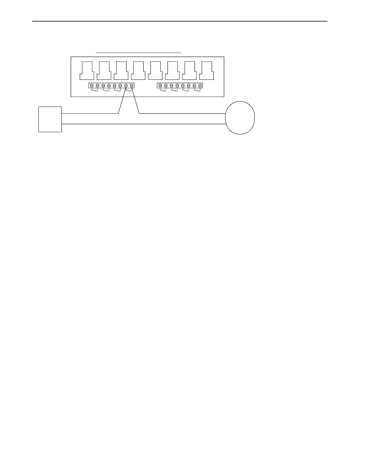
Fan Wiring
Mt1701-Fanwiring 10/01
TYPICAL WIRING OF OUTPUT RELAYS
RELAY IS SUPPOSED TO BE ON.
EACH RELAY'S CONTACTS ARE CLOSED WHEN THE OUTPUT THAT IS ASSIGNED TO THAT
SITUATION WHERE A FAN HAS BEEN ASSIGNED TO RELAY 4 IN THE SETUP SCREEN.
ALL OUTPUT RELAYS ARE SPST WITH DRY CONTACTS AS SHOWN. THIS SHOWS A TYPICAL
FAN A
FOR
BREAKER
CIRCUIT
L2
NOTE:
L1
#1
#1
#2 #3 #4
#3 #2 #4
FAN
#7
#5 #6 #7
#5 #6
#8
#8
Figure 111. Fan Wiring