MT1843B
105105
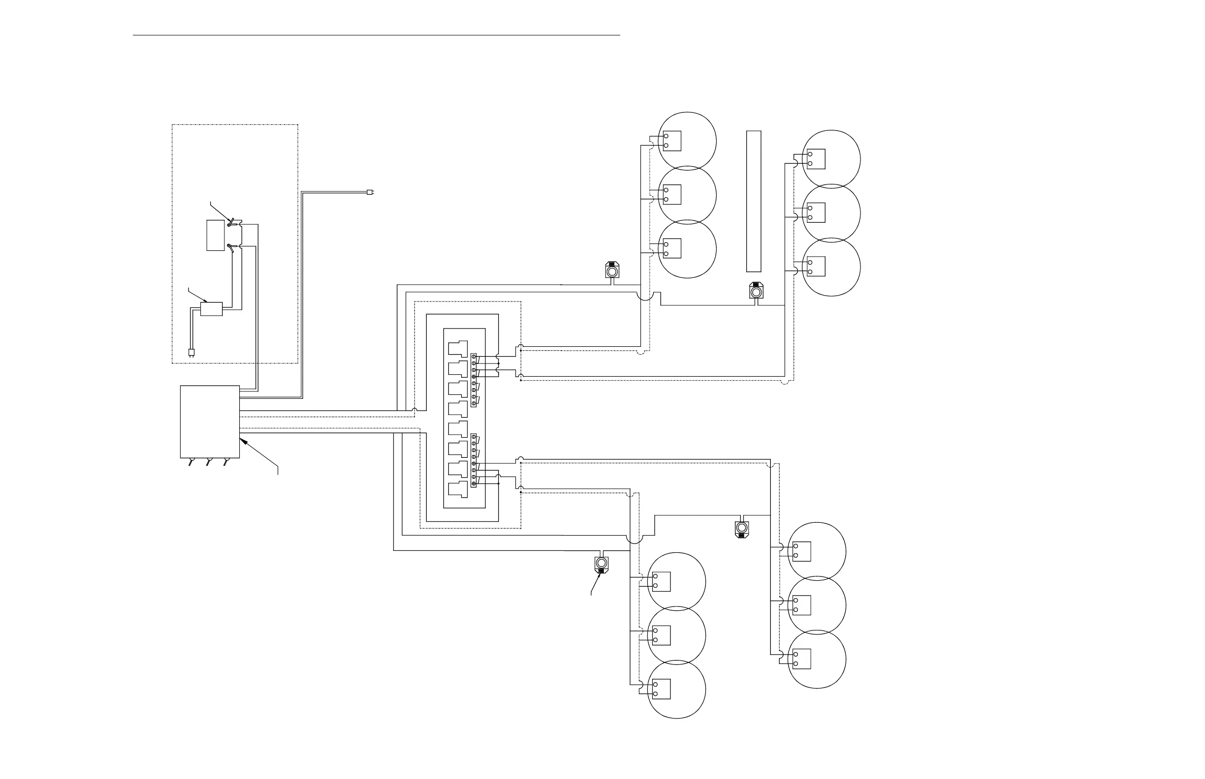
Brooder Wiring; 24 Volt, for 120 Volt AC Supply:
250 VA Transformer runs up to 40 Brooders (Pilot)
250 VA Transformer runs up to 18 Brooders(DSI)
Zone Three
THERMOSTAT
Zone One
WHITE WIRE (TH)
BLACK WIRE (TR)
TRTH TH
TH TR TRTH
BLACK WIRE (TR)
WHITE WIRE (TH)
BACK-UP
12V DC
24V AC OR
24V AC
24V AC
TH
BROODER
TR TR
BROODER
TH TR
24V AC
24V AC
24V AC OR
12V DC
Zone Two
WHITE WIRE (TH)
BLACK WIRE (TR)
(NOTE: USE 14-2 ROMAX WIRE)
BLACK WIRE (TR)
WHITE WIRE (TH)
Zone Four
24V AC OR
12V DC
TR TH
24V AC OR
12V DC
TR TH
24V AC
24V AC
TR TH TH
BROODER
TR
BROODER
24V AC
TR TH TR TH
24V AC
BROODERBROODER
BROODERBROODER
BROODERBROODER
BROODERBROODER
#2
#3
#4
#5 #6 #7 #8
Mt1701-Brooderwiring 01/02
TYPICAL WIRING OF OUTPUT RELAYS
Power Pack
Dual Zone
#1
#1
#2 #3 #4
MAIN POWER
ZONE 2
ZONE 1
BATTERY BACK-UP WILL NOT OPERATE
SPARK IGNITION BROODERS
BATTERY
12V DC
#7 #5 #6 #8
WARNING:
120V AC
WHITE
BLACK
CHARGER
12V DC
BLACK
RED
TRICKLE
120V AC
BACK-UP POWER SUPPL
ALIGATOR CLAMP FOR
See Dual Zone Power Pack Manual for Wiring
Figure 115. Brooder Wiring