Chore-Tronics® 2 Control Overview of Screens
MT1843B
41
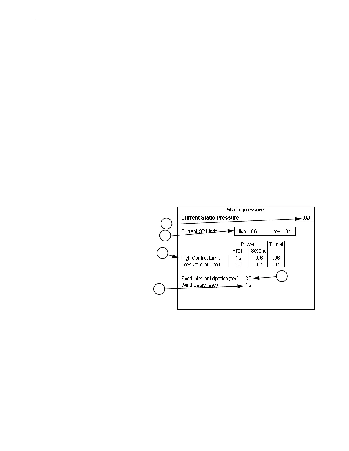
Screen 11: Static Pressure
Screen 11, (Figure 50) indicates the current static pressure plus provides the fields
that can be edited to set the Static Pressure Control limits and the wind delay. The
open and close Inlet Relays respond as required to keep the static pressure within the
Control limits while in the Power Mode and the open and close Tunnel Curtain
Relays do the same to control the static pressure during the Tunnel Mode. If it is not
desired to control the static pressure during the Tunnel Mode, the high control limit
in the Tunnel Mode must be edited to be .00. Static Pressure Control w/ Tunnel
Curtain during Power Mode-If in the Power Mode, there is inadequate inlet area to
keep the static pressure within the high control limits, the Tunnel Curtain will open
to give additional air inlet area. The Inlets are given continuous open signals as the
Tunnel Curtain takes over the responsibility of controlling the static pressure. The
static pressure has to be above the high Static Pressure Control limit continuously for
one minute with 3 or more Fans running for this to happen. Responsibility for Static
Pressure Control is passed back to the Inlets as soon as there are fewer than 3 Fans
running or the Tunnel Curtain cannot bring the static pressure back into the control
range (while closing) from the low side. The static pressure has to be below the low
Static Pressure Control limit continuously for one minute for this to happen.
Static Pressure Safety limits-When the static pressure stays above 0.20 for a
continuous minute, the Tunnel Curtain (if in Power Mode) and the Inlets (if in Tunnel
Mode) will open until the static pressure reduces below 0.20. Once the problem is
fixed and the static pressure reduces below 0.18, the Control returns to normal
operation. This situation will always result in a High Pressure Alarm.
1. Static Pressure Control limits-
The Static Pressure Control lim-
its are the values of static pres-
sure the Control attempts to
maintain by using the powered
Inlets, the Tunnel Curtain, or
both. A second level of Power
Mode static pressure can be cho-
sen in screen 13. The temperature
at which the second static pres-
sure takes over is entered in
screen 4. The Temperature Sen-
sor(s), (Inside Only), that mea-
sure that temperature is defined
in screen 13.
2. Wind delay-The wind delay is the
amount of time the static pres-
sure has to be continuously out-
side of the Control limits before
the appropriate open or close
Relay will be energized to bring the static pressure back within the control limits. The wind delay is
bypassed if a Fan or Fans turning on or off is what causes the static pressure to move outside the
Static Pressure Control limits.
3. Current Static Pressure-Current Static Pressure is the amount of static pressure currently measured by
the Control.
4. Current SP Limits-The Current SP Limits are the current high and low limit settings the Control is
using to control the inlets or tunnel curtain.
5. Fixed Inlet Anticipation-Fixed Inlet Anticipation is the amount of time the inlets will open prior to the
fans assigned to the Minimum Ventilation timer turn on. Fixed inlet anticipation must be set to YES
in the Setup-Control screen (Screen 14- Input tab).
MT1842-028 10/04
Figure 50. Screen 11: Static Pressure Screen
1
2
3
4
5