Control Installation Chore-Tronics® 2 Control
68
MT1843B
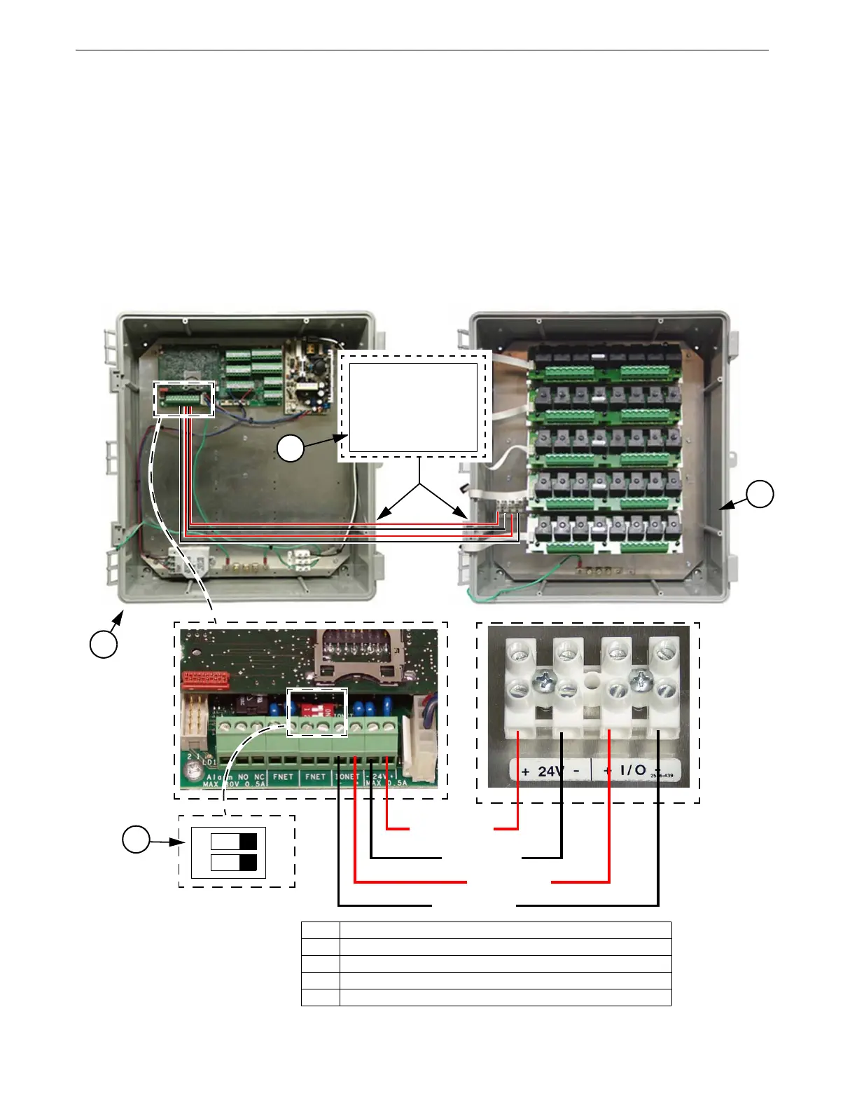
Do Not run I/O Net or 24 Vdc Twisted Pair wire close to and/or parallel
with line voltage wires. (See Figure 75)
The I/O Net terminals of the Main Box and the Relay box must be connected together
using the Non-Shielded Twisted Pair Wire (Chore Time Part no. 42208) included
within the Main Box. There is a Decal (Figure 74, Item 4) on the Main Box as well
as the Relay Box showing the location to route the I/O Net wires (Communication
Wires). I/O Net is polarity sensitive so be sure that the positive and negative I/O Net
terminals of both the Main Box and the Relay Box are connected properly (See
Figure 75). Make sure that DIP switch #1 on the I/O Board is in the ON position. The
24 Vdc must also be connected from the Main Box to the Relay Box using the
Twisted Pair wire included within the Main Box. Route the wires along with the I/O
Net Wires according to the Communication Wire Decals (Item 4) on the Boxes.
Warning!
ON
12
24 Vdc +
24 Vdc-
I/O Net +
I/O Net -
1
3
Item Description
1 Main Box
2 Relay Box
3 Dip Switch 1 (In On Position)
4 I/O Net and 24Vdc Wire Routing Decal (Communication Wire)
2
Figure 74. I/O Net and 24Vdc Wiring (Communication Wire)
4
2527-72
COMMUNICATION WIRES
Route Main Box / Relay Box
communication wires here.