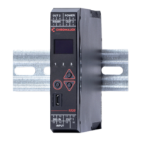
8
3.5 General Navigation & Editing
• Press or keys to navigate between param-
eters or menu items.
• Press to highlight a parameter value, ready for
editing.
• Press or to change the parameter val-
ue, then press within 60 seconds to confirm
change.
3.6 Mode (or Menu) Structure
There are 3 main modes (or menus) on the device –
Setup and Advanced Configuration Mode.
• User Mode - the live screen used for normal op-
eration. The process variable can always be seen in
this mode
• Setup Mode – allows access to the most important
parameters
• Advanced Configuration Mode - access all param-
eters via sub-menus
Setup Mode - press & .
Advanced Configuration - press & .
Never connect the instrument’s configuration
socket directly to a USB port as it will damage
the controller.
3.7 Returning to Operator Mode
Press & to move back one level
From a sub-menu you will need to do this twice; once
to return to Advanced Configuration Mode then again
to exit. After 120 seconds without key presses the unit
returns automatically to the first Operator mode screen.
3.8 Mode Access and Lock Codes
Separate lock codes can be set for the Setup mode
and for the Advanced Configuration mode.
• Setup mode lock code – default 10.
• Advanced Configuration mode lock code – default
20.
Hold the button while powering up for a read-only
view of lock codes.
3.9 Use of the Controller for Non-
Temperature Applications
In the majority of applications this controller will be
used for temperature sensing, either via a sensor or a
linear DC input, which use heat and cool. However this
controller can be used for other types of processes.
If your process is not a temperature then the param-
eters labelled as “HEAT”refer to reverse acting outputs
used to increase the process value and “COOL” to de-
crease the process value.
As an example you may have a system that reads and
controls humidity. The “HEAT” output drives the hu-
midifier and the “COOL” output drives the de-humidifi-
er. Use the “HEAT” parameters to control the humidifier
and the “COOL” parameters to control the de-humid-
ifier.
Often the “HEAT” and “COOL” is referred to as “Pri-
mary” and “Secondary” on other controllers.
3.10 Controller Transmitter Function
The Standard 1020 & 1030 model can be used as a
“transmitter” to retransmit the process value or con-
troller setpoint via Output 3, if the linear option is fitted.
The parameter Usage in the Linear Output sub-menu
can be set to PV Retransmit or SP Retransmit.
In the Display menu, the parameter Transmitter can be
used to enable Transmitter view. This hides the Set-
point from view.
Control functions will remain active if
they have been configured.

 Loading...