51
15 Serial Communications
15.1 Supported Protocol
The unit supports Modbus RTU protocol through the
RS485 interface.
For a complete description of the Modbus protocol refer
to the description provided at http://www.modbus.org/
15.2 RS485 Configuration
The RS485 address, bit rate and character format are
configured via the front panel from the Communica-
tions Sub-menu.
Data rate: 4800, 9600 (default), 19200 or 38400 bps
Parity: None (default), Even or Odd
Device Address: 1 to 255 - See RS485 Device Ad-
dressing
For successful communication the
master device must have matching
communications settings.
15.3 RS485 Device Addressing
The instrument must be assigned a unique device ad-
dress in the range 1 to 255. This address is used to rec-
ognise Modbus queries intended for this instrument.
Except for globally addressed broadcast messages
sent to device address 0, the instrument ignores Mod-
bus queries from the master that do not match the
address that has been assigned to it. These global
queries are processed when received but no response
messages are returned.
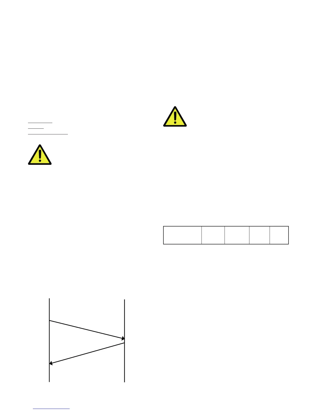
15.4 Link Layer
A Query (or command) is transmitted from the Modbus
Master to the Modbus Slave. The slave instrument as-
sembles the reply to the master.
MASTER
QUERY
RESPONSE
A message for either a QUERY or RESPONSE is made
up of an inter-message gap followed by a sequence
of data characters. The inter-message gap is at least
3.5 data character times - the transmitter must not
start transmission until 3 character times have elapsed
since reception of the last character in a message, and
must release the transmission line within 3 character
times of the last character in a message.
Three character times is approximately
0.75ms at 38400 bps, 1.5ms at 19200 bps,
3ms at 9600 bps and 6ms at 4800bps.
Data is encoded for each character as binary data,
transmitted LSB first. For a QUERY the address field
contains the address of the slave destination. The slave
address is given together with the Function and Data
fields by the Application layer. The CRC is generated
from the given address, function and data characters.
For a RESPONSE the address field contains the ad-
dress of the responding slave. The Function and Data
fields are generated by the slave application. The CRC
is generated from the address, function and data char-
acters.
The standard MODBUS RTU CRC-16 calculation em-
ploying the polynomial 216+215+22+1 is used.
Inter-message
gap
Address
1 char.
Function
1 char.
Data
n char.
CRC
Check
2 char.

 Loading...
