18
7.3 User Calibration Menu (Applicable to Standard and Extrusion Models)
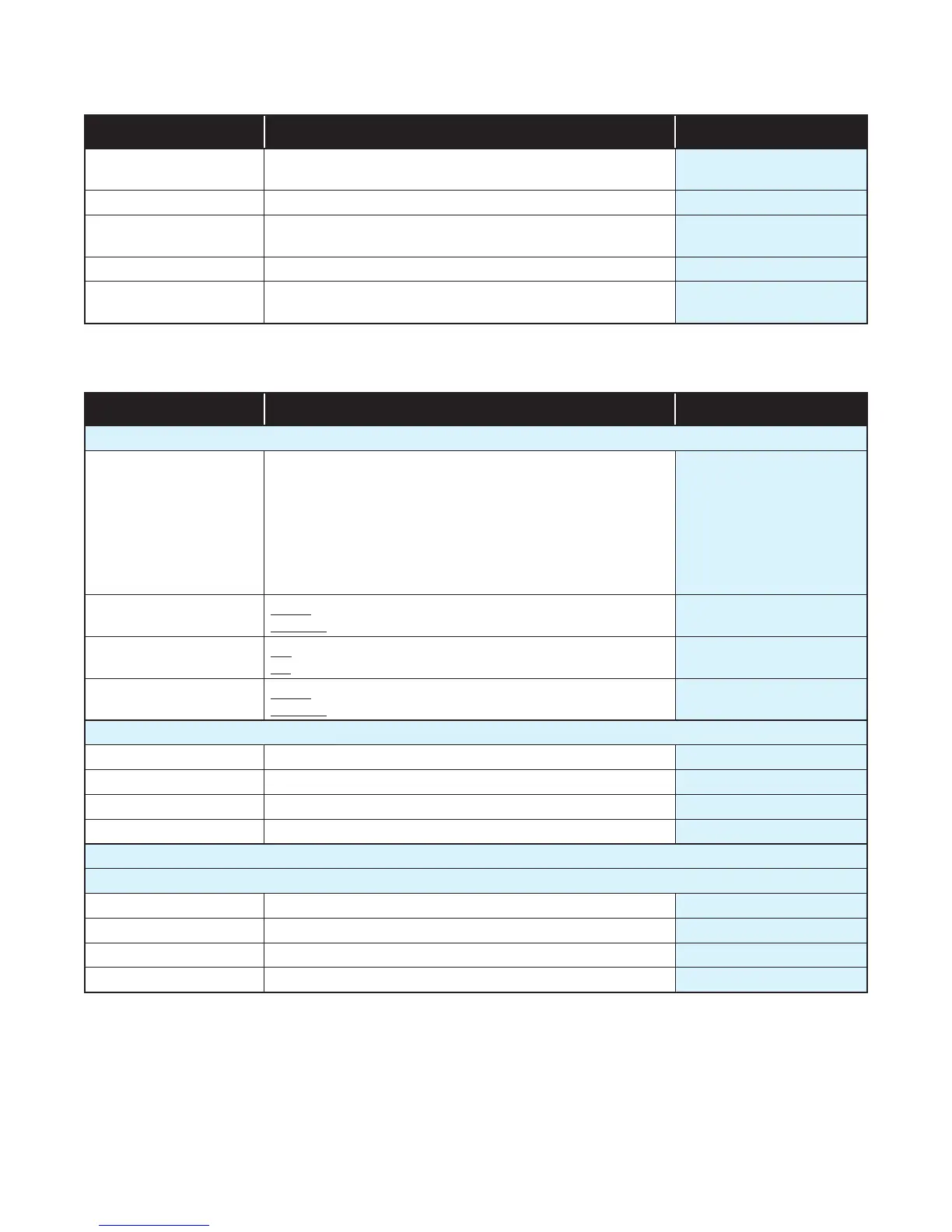
Parameter Description Default Value
Offset Shifts the input value up or down by this offset value,
across the entire range.
0
Low Point Enter value at which the low point error was measured. Lower Limit
Low Offset Enter equal, but opposite offset value to the observed
low point error.
0
High Point Enter value at which the high point error was measured. Upper Limit
High Offset
Enter an equal, but opposite offset value to the observed
high point error.
0
7.4 Outputs Menu (Applicable to Standard and Extrusion Models)
Parameter Description Default Value
Output 1 Sub-menu
Usage
Heat (Reverse acting control)
Cool (Direct acting control)
Non Linear Cooling (Extrusion model only)
Alarm 1
Alarm 2
Alarm 1 or 2
(i.e. logical ‘OR’ of Alarm 1 & 2)
Loop Alarm
Heat
Alarm Action
Direct - Output active when alarm triggers
Reverse - Output active when alarm is not triggered
Direct
Latching
Off - Alarm doesn’t latch
On – Alarm latches (remains in active state until cleared)
Off
LED Indicator Direct - LED Indicator lit when output is active
Reverse - LED Indicator lit when output is inactive
Direct
Output 2 Sub-menu
Usage Same options as Output 1 - Usage Alarm 1
Alarm Action Same options as Output 1 - Alarm Action Direct
Latching Same options as Output 1 - Alarm Latching Off
LED Indicator Same options as Output 1 - LED Indicator Direct
Output 3 Sub-menu
If a Relay or SSR drive is fitted in Output 3, this sub-menu is visible.
Usage Same options as Output 1 Usage Alarm 2
Alarm Action Same options as Output 1 - Alarm Action Direct
Alarm Latching Same options as Output 1 - Alarm Latching Off
LED Indicator Same options as Output 1 - LED Indicator Direct

 Loading...
