25
8.3 Base Input Calibration
Calibration of the input is carried out during manufac-
ture, and for most applications, re-calibration is not
required during the lifetime of the instrument. User
1-point and 2-point calibration can be carried from the
User Calibration menu.
Re-calibration of the internal base values
is possible, but should only be attempted
by qualified personnel as it overwrites
the factory calibration.
A suitable calibration signal source is required for each
input type. To verify the accuracy of the instrument or
carry out re-calibration, the input sources listed below
are required, with better than ±0.05% of the reading
accuracy:
1. DC linear inputs: 0 to 50mV dc, 0 to 10V dc & 0 to
20mA dc.
2. Thermocouple inputs - complete with 0ºC reference
facility, appropriate thermocouple functions and
compensating leads (or equivalent).
3. RTD inputs: decade resistance box with connec-
tions for three-wire input (or equivalent).
8.4 Calibration Check
1. Set up the instrument to the required input type.
2. Note down, then remove any single or two-point
calibration values by setting them to zero.
3. Power up the instrument and connect the correct
input leads, to the correct terminals.
4. Leave powered up for at least five minutes for RTD
and DC linear inputs, or at least 30 minutes for ther-
mocouple inputs.
5. After the appropriate delay for stabilization has
elapsed, check the calibration by connecting the
appropriate input source and checking a small
number of cardinal points.
6. Repeat the test for all required input types.
7. Check the results against the specification stated
for the required input type.
8. Reinstate the calibration values removed at step if
they are still appropriate.
Make the connections using the correct ther-
mocouple cable type. For all other input types
use copper cable. Using the wrong type of ca-
ble will cause incorrect readings. This is espe-
cially important with thermocouple sensors.
8.5 Base Calibration Procedure
Input calibration is carried out in five phases as shown
below, each phase corresponds to an input range of
the instrument.
The 50mV phase must be calibrated first be-
fore any other range(s).
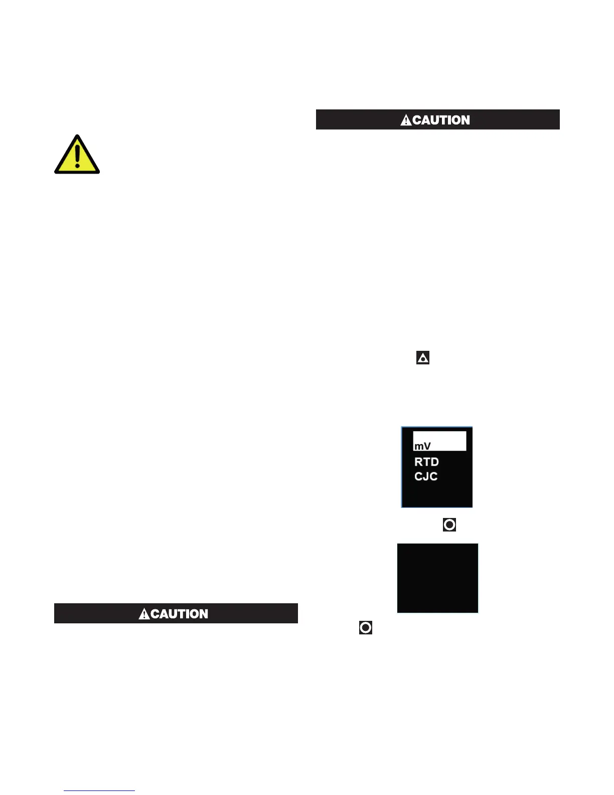
Calibration phases:
i. mV for 50 mV
ii. V for 10 V
iii. mA for 20 mA
iv. RTD input (200Ω ohm resistance source)
v. CJC (K type thermocouple source at 0ºC required)
For Extrusion models phase ii and iii (V & mA) are omit-
ted.
8.6 Calibrating the mV Input
1. Check your calibration source is connected to the
correct terminals on the 1020 Rail. For 50mV, con-
nect your mV source +ve to pin 14 and -ve to pin 15
located on the bottom rear connector – see wiring
section.
2. Press and hold the button, whilst the instrument
is powering up, until the display shows the screen
starting with mV. Be patient, may take approximate-
ly 30 seconds.
3. In the calibration phase menu displayed, highlight
mV from the list.
>mV Input
userCAL
Press enter
to start
4. With mV selected, press . The following screen
will appear:
>mV Input
userCAL
Press enter
to start
5. Press . You should see the messages Starting
Calibration, followed by Calibration in Progress.
A dot moves across the display to show the prog-
ress.
6. If the input is wrongly connected or an incorrect sig-
nal is applied the calibration will be aborted and the
display will show Calibration FAIL. The previous
calibration value will be retained.

 Loading...
