37
13.4 Limiter Operator Mode & Screens
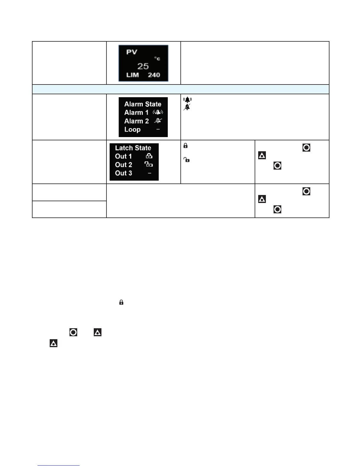
User Screen PV – top
Temperature & Unit – centre & right.
LIM & Limit Setpoint - bottom
IMPORTANT: Visibility for parameters below must be set to Show in the Operator menu.
Alarm State
Alarm triggered
Alarm configured, but not triggered
– Alarm not set
Latch State
Output Latched
Latch set, but output
not Latched
– Latch not set
To clear press
then
to select Yes.
Press to accept.
Maximum PV
Screens show the Maximum & Minimum PV reached.
To clear press
then
to select Yes.
Press to accept.
Minimum PV
13.5 Limiter Output Latching
When an SSR drive or Relay output is configured to
‘latch’ it will remain on after the limit or alarm condi-
tion has cleared. The latch enable parameter, Output
Latching, needs to be ON for outputs you want to
latch.
Limiter Clearing Latched Outputs
The latch condition, shown by in the Latch State
screen, needs to be cleared either via a Modbus com-
mand, digital input or from the front panel.
To clear latches from the front panel, in the Latch State
screen, press then to select Yes.
Press to accept.
Limiter Start-up Latch
The parameter Startup Latch, is only present on the
limiter model. It determines how latching outputs be-
have when the unit is powered up. It is set individually
for each of the outputs (limit and/or the 2 alarms). The
three possible modes are as follows:
• Reset Latch: The latch state is not remembered
when the unit is powered off. The latch becomes
active again only if the associated limit / alarm state
is present at or after power-on.
• Always Latch: The instrument will always power on
with the chosen output in the latched state, even if
the associated limit or alarm is not active.
• Last Latch: The latch state is remembered on
power down. Any output that was latched on power
down it will still be latched when power is restored,
even if that limit or alarm is no longer active.
Note: If a limit or alarm state exists at power-up,
previously unlatched outputs always activate im-
mediately, no matter how the Start-up Latch has
been set.
Limiter Sensor Break Detection
If a “Sensor break” is detected on the Limiter model,
this always triggers the Limit exceed condition, place
the process into a safe state. Correct the input prob-
lem, then unlatch the limit output to resolve this.
Limiter Output 3 – Linear, Relay or SSR drive
• If the linear output is fitted to Output 3 on the Limiter
model, it can only be used for a PV re-transmit func-
tion.
• If a relay or SSR drive is fitted in Output 3 then it is
fixed as Alarm 2.

 Loading...
