24
8 Calibration Mode
It is possible to calibrate the controller to compensate
for sensor errors and other tolerance errors in the sys-
tem. This is achieved using the calibration mode. The
calibration mode allows an offset to be applied in one
of two ways. The method used will be dependent on
the process application.
These methods do not alter the internal
instrument calibration. Set the offset
values back to zero to restore standard
measured values. Re-calibration of the
internal base calibration is also possible,
but should only be attempted by qualified
personnel as it overwrites the factory
calibration – see Base Input Calibration
below.
8.1 Single Point Calibration (PV Off-
set)
This is a ‘zero offset’ applied to the process variable
across the entire span. Positive values are added to the
reading, negative values are subtracted. It can be used
if the error is constant across the range, or the user
is only interested in a single critical value. To use, se-
lect Single Point Calibration from the input calibration
menu, and simply enter a value equal, but opposite to
the observed error to correct the reading.
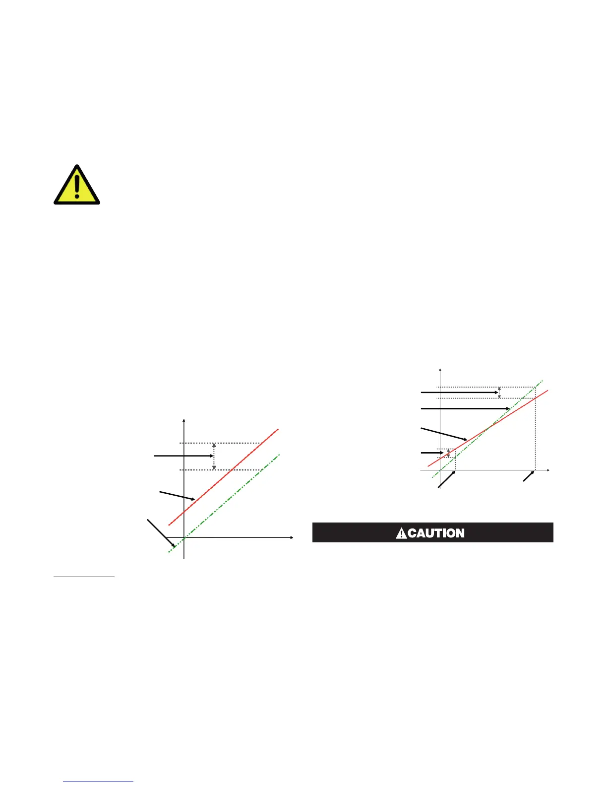
This example shows a positive offset value.
Single Point ‘Offset
Calibration’ value
New Displayed Value
Original Displayed Value
For example: If the process displays 27.8 when it
should read 30, The error is -2.2 so an applied offset
of +2.2 would change the displayed value to 30. The
same offset is applied to all values, so at 100.0 the new
displayed value would be 102.2.
8.2 Two Point Calibration
This method is used where an error is not constant
across the range to change the calibration slop. Sepa-
rate offsets are applied at two points in the range to
eliminate both “zero” and “span” errors.
1. Measure and record the error at a low point in the
process.
2. Measure and record the error at a high point in the
process.
3. Go to the first two-point input calibration screen.
a. Enter the desired low point value as the Calibra-
tion Low PV value.
b. Enter an equal, but opposite value to the ob-
served error as the Calibration Low Offset to cor-
rect the error at the low point.
4. Go to the second two-point input calibration screen.
a. Enter the desired high point as the Calibration
High PV value.
b. Enter an equal, but opposite value to the ob-
served error as the Calibration High Offset to
correct the error at the high point.
New Displayed Value
Calibration High Offset
Calibration Low Offset
Calibration High
Process Value
Calibration
Low Process Value
Original Displayed Value
Choose values as near as possible to the bot-
tom and top of your usable span to achieve
maximum calibration accuracy. The effect of
any error can grow at values beyond the cho-
sen calibration points.
The single and two-point calibration methods can be
used together, if you need to change the calibration
slope and offset the zero point simultaneously.

 Loading...
