4
2.8 Terminal Wiring
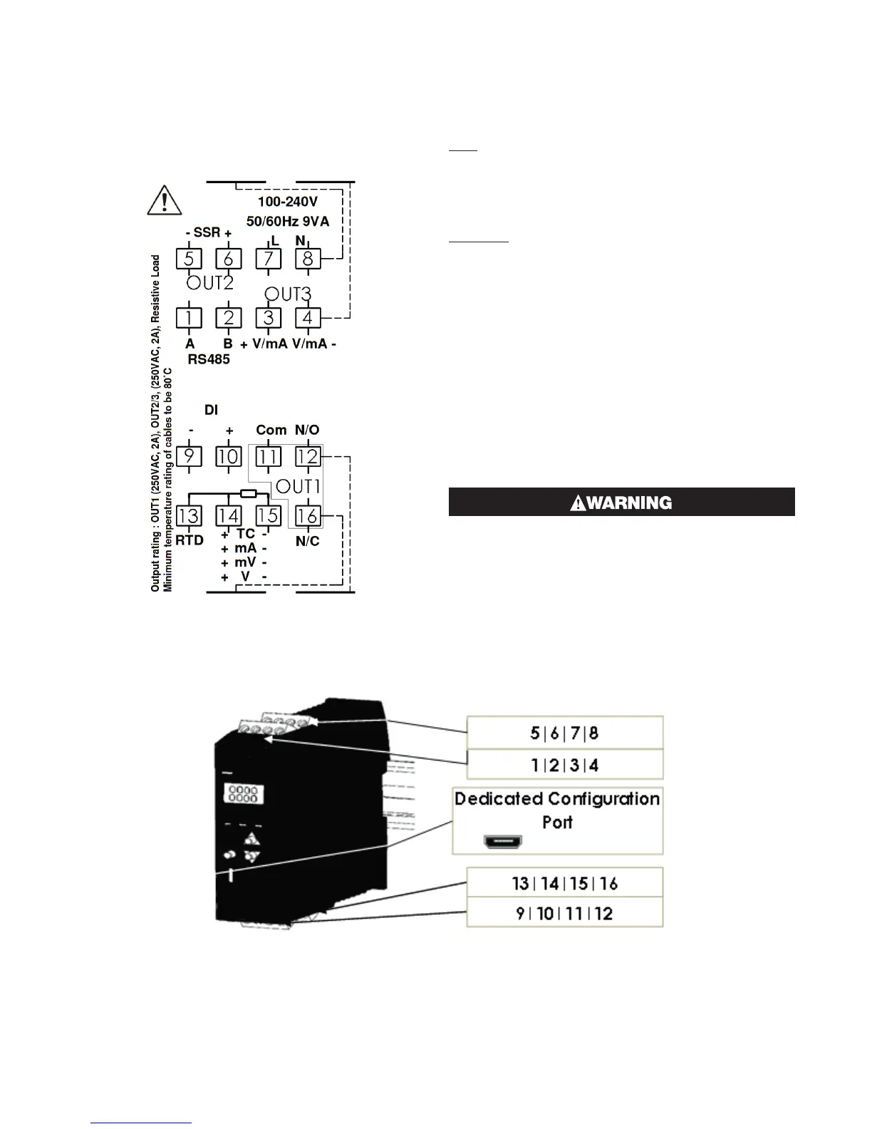
The diagram shows all possible option combinations.
Please check the product configuration before wiring.
Dedicated Configuration Socket (on bottom of the in-
strument)
The wiring label shows the power requirements, con-
nector positions and terminal number.
This example is:
TOP
1 & 2 Rear = RS485 Comms
3 & 3 Rear = Linear Out 3
5 & 6 Front = SSR Driver Out 2
7 & 8 Front = 100-240VAC power.
BOTTOM
9 & 10 Rear = Digital Input
11, 12 Rear & 16 Front = Relay Out 1
13, 14 & 15 Front = Process Input
2.9 Power Connection
To avoid damaging your instrument it is critical the
power connection is made to the correct terminals
Power is connected to pins 7 & 8.
Top, rear connector on the right-hand side.
(front connector omitted from picture for clarity)
The green LED shows when power is correctly con-
nected.
NEVER DIRECTLY CONNECT THIS SOCKET TO
A USB PORT.
A configuration socket to USB adaptor can be obtained
from your supplier.

 Loading...
