26
7. If the calibration was successful, the display shows
Calibration PASS.
8. To clear the Pass or Fail pop-up press and .
9. Now press and to return to the calibration menu.
From here either select another calibration phase,
or press & again to return to the operator
screen.
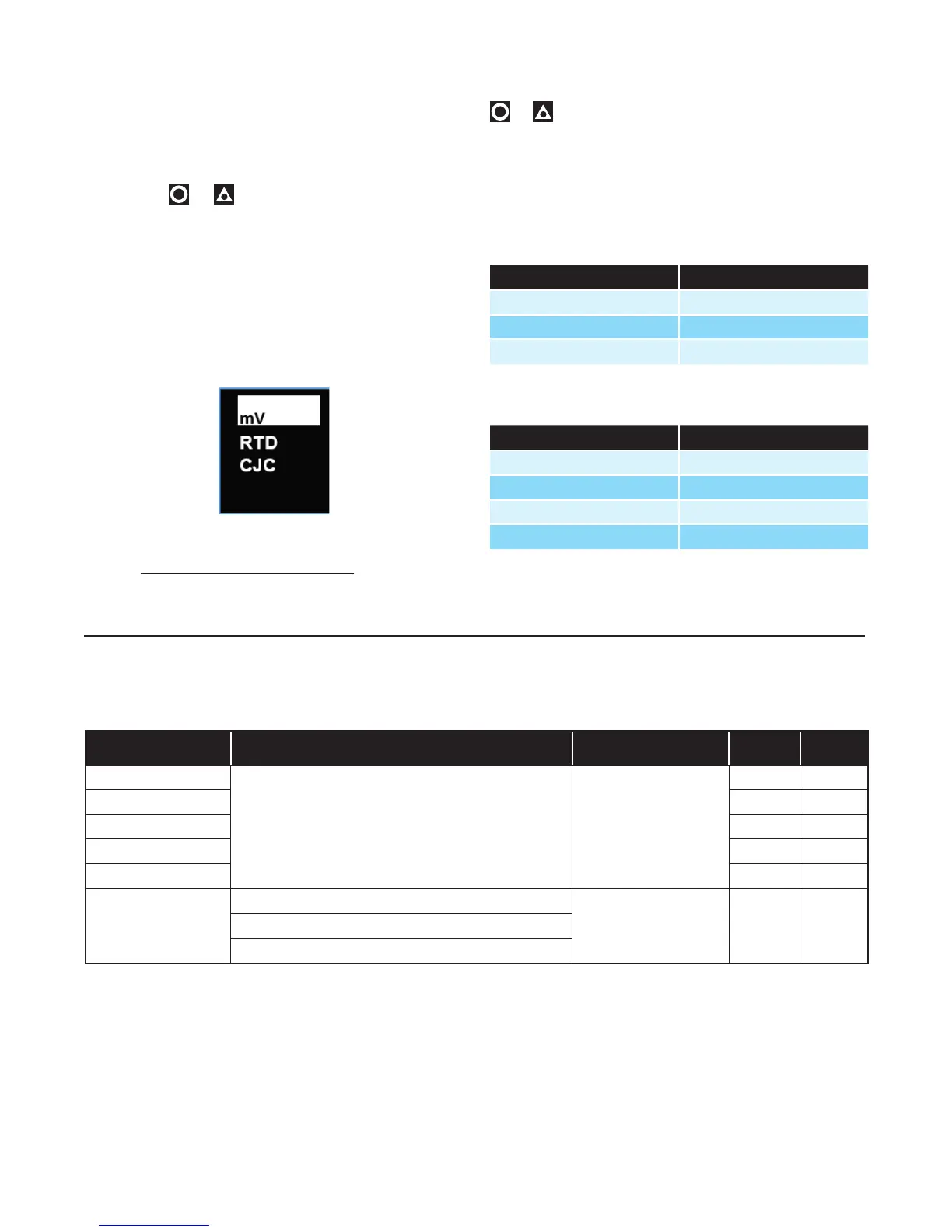
8.7 Calibrating Other Input Types
The 50mV calibration must be carried out first. After
this, you can select the other types in turn. The oth-
er calibration phase procedures are similar to the mV
phase above, but ensure that the correct input signal
and connections are used – see the wiring section for
connection details.
Note: When calibrating the RTD input type, connect an
accurate 200Ω resistance source across pin 14 and pin
15, and link between pin 13 and pin 14 to replicate the
3-wire compensating lead.
When you have completed the required phases, press
& to exit back to the operator screen.
The Calibration Mode automatically exits if there is no
button activity for five minutes.
8.8 Calibration Input States
Each input can have one of three states:
Description State Shown
Input not calibrated noCAL
Factory calibrated factCAL
User calibrated userCAL
8.9 Calibration Progress
Description Popup
Initial popup Starting calibration
During calibration Calibration in progress
Calibration succeeded Calibration PASS
Calibration failed Calibration FAIL
8.10 Calibration Modbus Addresses
The following Modbus addresses can be used to initiate the calibration phases and read back the status.
Description Comment Dec Hex
50mV Calibration
Write 0xCAFE to start the
calibration for the selected input.
Write Only
1700
6A4
10V Calibration
1701
6A5
20mA Calibration
1702
6A6
RTD Calibration
1703
6A7
CJC Calibration
1704
6A8
Calibration Status
0x0000 - Calibration Failed
Read Only
1770
6EA
0xCAFE - Calibration Busy
0xFFFF - Calibration Successful

 Loading...
