Troubleshooting
6-12 Manual 0-5186
WELDSKILL 250, 350 TROUBLESHOOTING
10. Inch
The INCH button is connected to CN6 terminals 7 & 8.
When the INCH button is pressed U5 A pin 3 is pulled high, causing U5 pin 1 to go high, enabling motor drive
operation.
As Q7 / U1B / Q3 do not change state, the contactor & solenoid are not activated. Only the wire drive motor
operates when the INCH button is pressed.
11. Latch
The LATCH switch is connected to CN7 terminals 1 & 2.
When the LATCH switch on the internal panel is open, U2 pin 4 is held low by R24.
When the trigger is pressed, U7 is turned on via R51 & R12. The output of U7 will be closed and U8 pin 1 will
be high. U8 pin 4 will also be high putting a positive going clock signal into U2. The output of U2, pin 1,changes
state from low to high, turning on Q8 (the trigger transistor) via D25.
When the trigger is released, U7 will turn off, and U8 pin 4 will go low. The output of U2 will still be high and
the trigger transistor Q8 will still be on, keeping the machine triggered.
When the trigger is pressed, U7 is turned on via R51 & R12. The output of U7 will be closed and U8 pin 1
will be high. U8 pin 4 will also be high putting a positive going clock signal into U2. The output of U2, pin 1,
changes state from high to low, turning off Q8 (the trigger transistor) via D25.
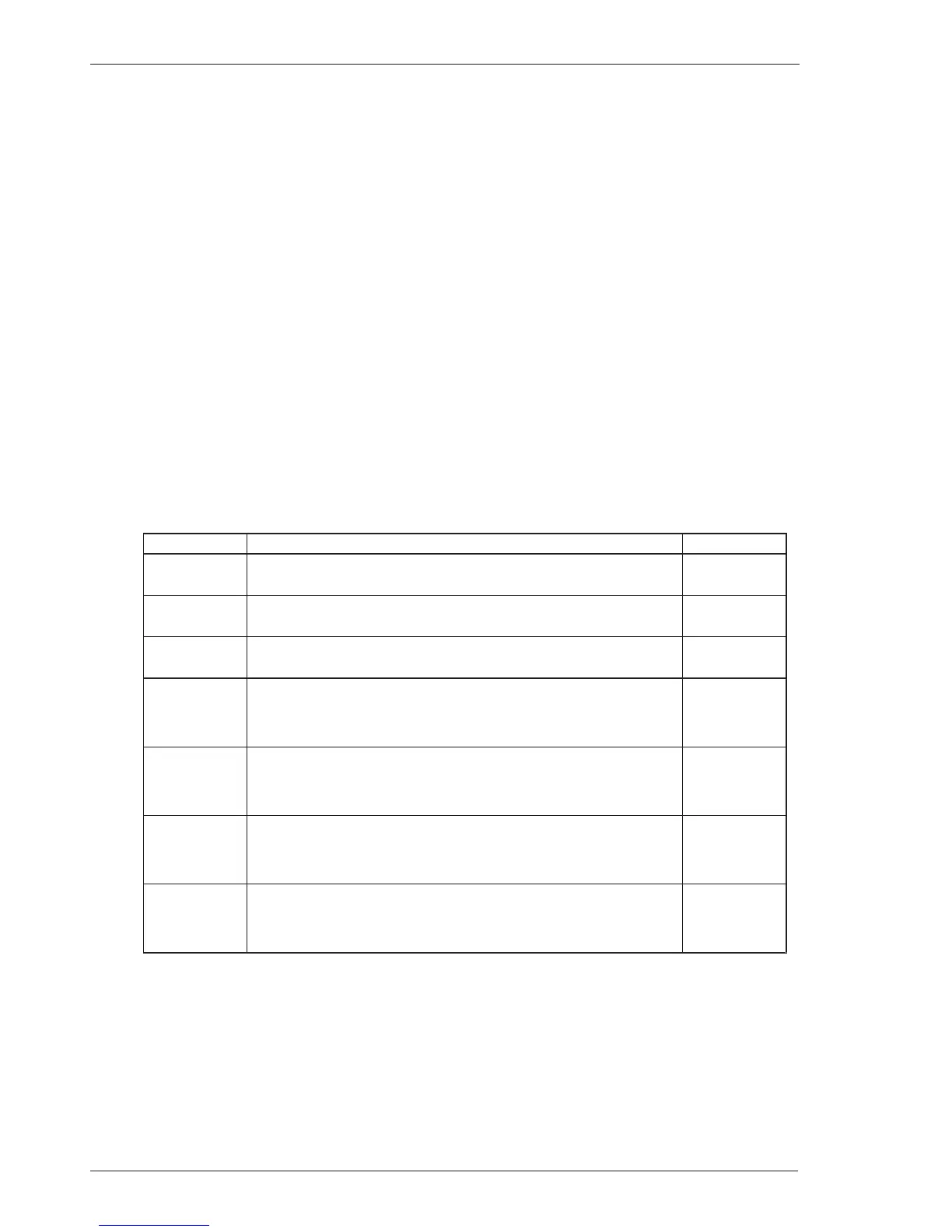
12. Inputs to Control PCB
Terminal Input Descriptions
Reference
CN3/1
AC supply for circuit
CN3/1= 20 Vac
CN3/2
CN3/3
AC supply for circuit
CN3/3= 20 Vac
CN3/2
CN5/1
AC supply for wire drive motor
CN5/1= 30 Vac
CN5/2
CN7/3
Input signal for torch trigger
CN7/3 = 0 Vdc (Torch trigger switch open)
CN7/3 = 8 to 12 Vdc (Torch trigger switch closed)
CN3/2
CN2/2
Input signal for thermostat
CN2/2 = 8 to 12 Vdc (Thermostat closed)
CN2/2 = 0 Vdc (Thermostat open)
CN3/2
CN8/2
Reference signal from wirespeed potentiometer wiper
CN8/2 = ~1.1 Vdc (Wirespeed potentiometer minimum)
CN8/2 = ~7.0 Vdc (Wirespeed potentiometer maximum)
CN3/2
CN7/1
Latch switch
CN7/1= ~0 Vdc (Latch switch open)
CN7/1= ~11.5Vdc (Latch switch closed)
CN3/2
Table 6-14 Inputs to Control PCB 7978050