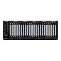
Setting Up the CH2 Tester 10
2. Plug the power cord into the additional scanner. A power connection is needed for each
scanner chassis.
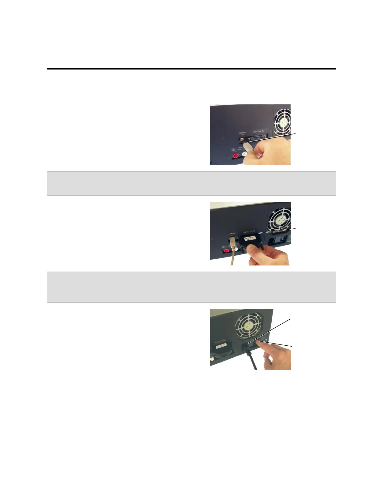
1. Insert one end of the USB cable into the USB
port on the back of the Base Unit. Insert the
other end into a USB port on your computer.
Note: For more reliable tester operation, connect the tester’s USB port directly to the PC’s
USB connect and not a USB Hub.
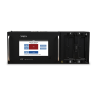
2. Connect the HV Interlock Override to the
Digital I/O Connector on the Base Unit.
Note: CH2 testers made after March of 2007, have HV interlock capability. An interlock helps
protect operators from high voltage during the high voltage test. For more information on
interlocks, search the word “interlock” in the Easy-Wire help system.
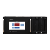
3. Plug the power cord into the Base Unit’s power
connector. Make sure the back panel power
switch is in the ON position.
Power switch
(not found on
every tester)