EasyManua.ls Logo

Cirris CH2 - Building an HV Interlock

Cirris CH2
64 pages
Print Icon
To Next Page IconTo Next Page
To Previous Page IconTo Previous Page
Loading...
xHV Power Supply 33
Building an HV Interlock
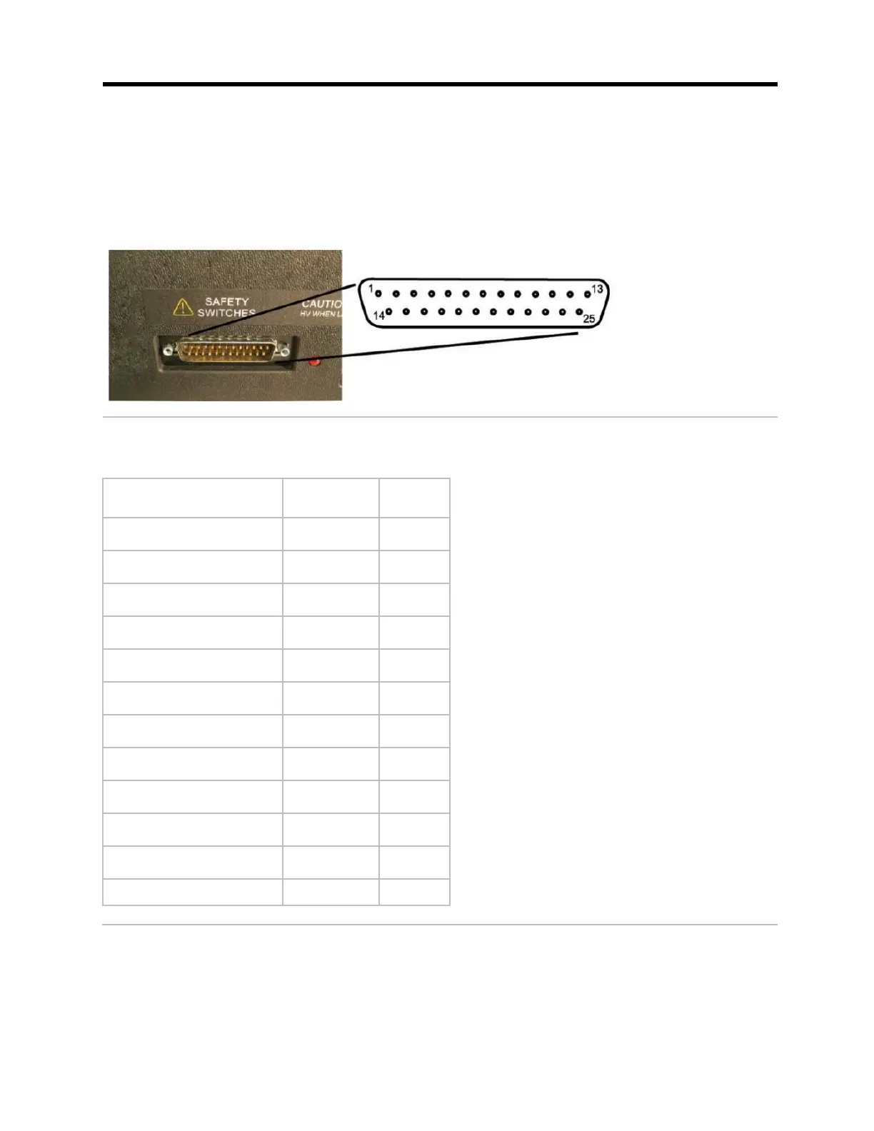
On the rear panel of your xHV Power Supply is a connector called, “Safety Switches.” This
connector must be used to wire Interlock Safety switches and an Emergency Shutoff switch
to the xHV Power Supply. The switches provided by Cirris are identified as Interlock Safety
1, Interlock Safety 2, and Emergency Shutoff (E-Stop).
The diagram below displays the “Safety Switches” connector pin out.
Each safety switch has four signals: Drive+, Drive-, Sense+, and Sense-. The table below
displays the switch name, signal, and pin number of the HV Safety Interlock.
Switch Name
Signal
Pin #
Interlock Safety 1
Drive+
19
Interlock Safety 1
Drive-
6
Interlock Safety 1
Sense+
18
Interlock Safety 1
Sense-
5
Interlock Safety 2
Drive+
14
Interlock Safety 2
Drive-
1
Interlock Safety 2
Sense+
2
Interlock Safety 2
Sense-
15
Emergency Shutoff
Drive+
13
Emergency Shutoff
Drive-
25
Emergency Shutoff
Sense+
12
Emergency Shutoff
Sense-
24

Other manuals for Cirris CH2

Related product manuals