3-16
Cisco 7600 Series Router Installation Guide
OL-4503-26
Chapter 3 Installing the Cisco 7600 Series Router
Installing the Cable Management System (Cisco 7609 Router and Cisco 7609-S Router Only)
Note The cable management system is included only in the accessory kit for the Cisco 7609
router(CABLETRAY-09=) and Cisco 7609-S router(CABLETRAY-09S=). Do note that the extended
and the standard cable guides are included in the CABLETRAY-09= that is shipped with Cisco 7609
routers, and only the extended cable guide is included in the CABLETRAY-09S= shipped with Cisco
7609-S routers.
Note The cable management system is shipped with the extended cable guide installed, but can be used with
the supplied standard cable guide. Use the extended cable guide with Ethernet and Fast Ethernet modules
(24 to 48 ports) using 10/100 cable. Use the standard cable guide with OSMs or other low port-density
modules (up to 16 ports) using fiber and coax cable. We recommend that you install the cable
management system before replacing the cable guide. See the
“Replacing the Cable Guide” section on
page 3-17 for replacement procedures.
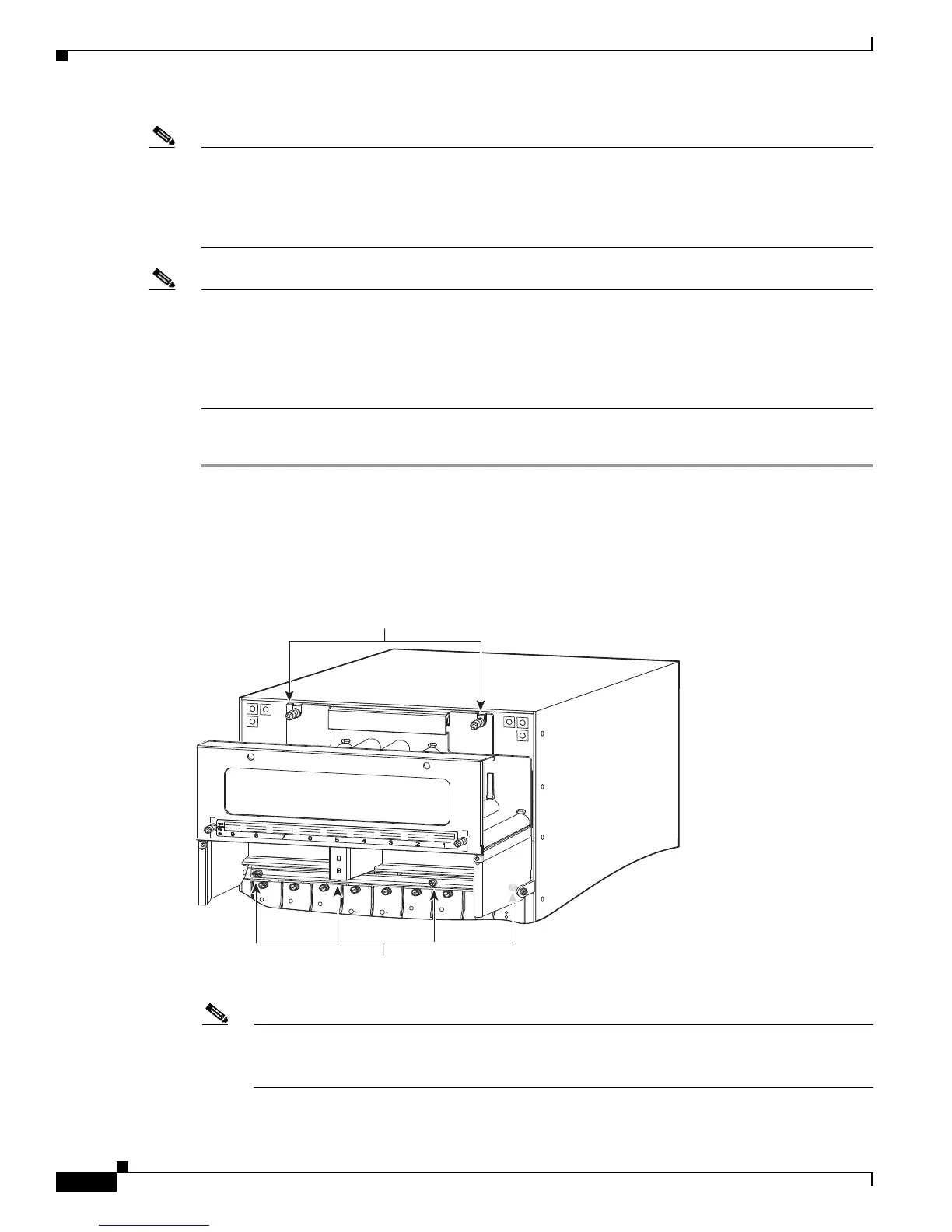
To install the cable management system, perform these steps:
Step 1 Place the cable management system against the chassis, as shown in Figure 3-16, and tighten the captive
installation screws.
Step 2 Assure that the hinge is flat against the chassis, and install four 6x32 screws to secure the back plate to
the chassis.
Figure 3-16 Installing the Cable Management System
Note To route the cables through the cable guide, remove the front panel and attach the interface
cables to the modules. See the
“Attaching the Interface Cables” section on page 3-25 for
information on attaching the interface cables.
SUPERVISOR2
WS-X6K-SUP2-2GE
S
T
A
T
U
S
S
Y
S
T
E
M
SUPERVISOR2
WS-X6K-SUP2-2GE
S
T
A
T
U
S
S
Y
S
T
E
M
S
W
IT
C
H
F
A
B
R
IC
M
D
L
S
T
A
T
U
S
W
S
-
C
6
5
0
0
-
S
F
M
S
W
I
T
C
H
F
A
B
R
IC
M
D
L
S
T
A
T
W
S
-
C
6
5
0
0
-
S
F
M
O
C12 POS MM
OSM-40C12-POS-MM
S
T
A
T
U
S
O
C12 POS M
M
OSM
-40C
12-POS-MM
S
T
A
T
U
S
OC12 POS M
M
OSM-40C12-PO
S-M
M
S
T
A
T
U
S
8 PORT OC3 POS MM
OSM-8OC3-POS MM
STATUS
8 PORT OC3 POS
OSM-8OC3-POS MM
STATUS
85713
FA
N
STA
TUS
FAN
1
FAN
2
CISCO 7609
Captive installation screws
Hin
e screws