B-10
Cisco 7600 Series Router Installation Guide
OL-4503-26
Appendix B Connector and Cable Specifications
Cable Specifications
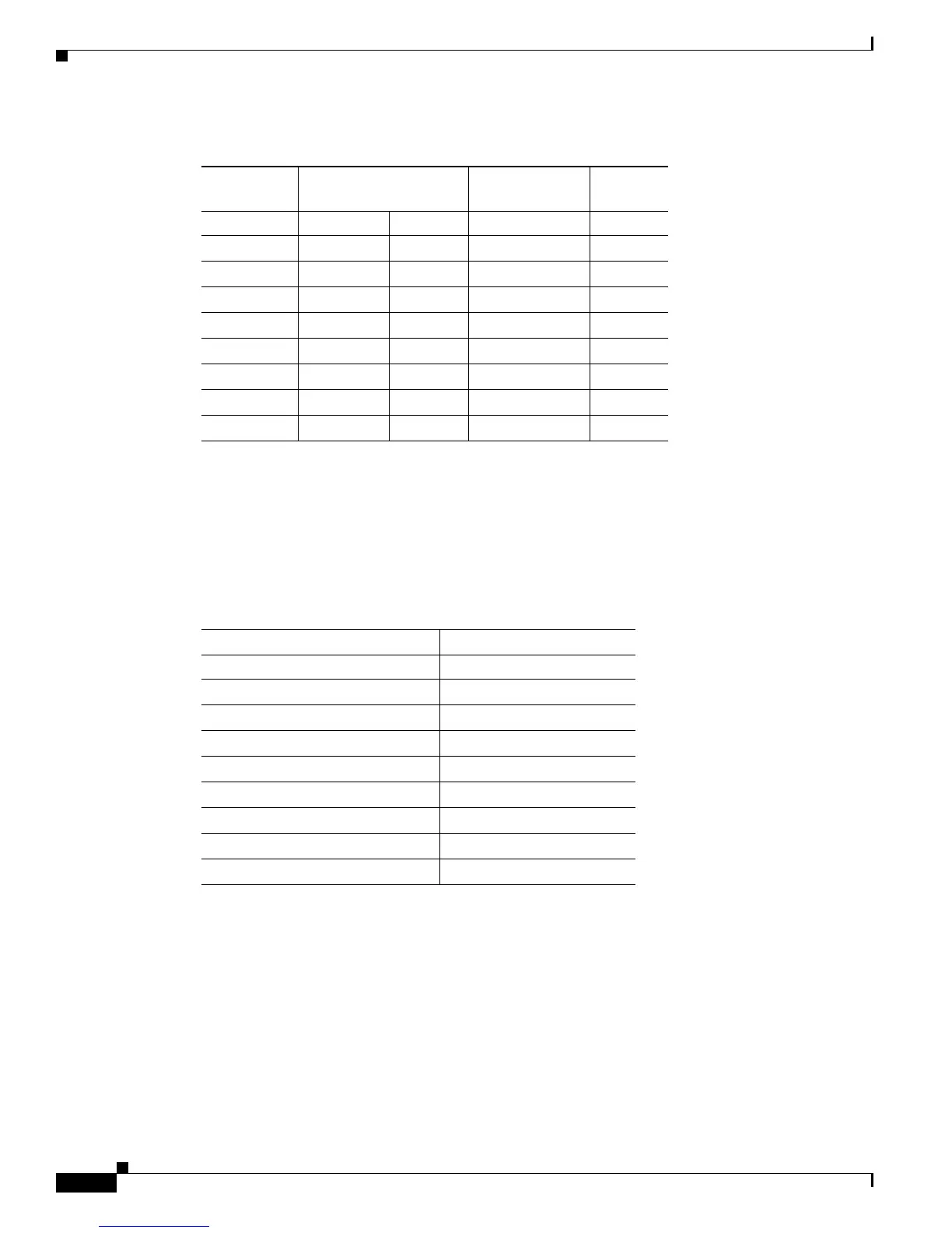
Console Port Mode 2 Signaling and Pinouts
This section provides the signaling and pinouts for the console port in mode 2 (port mode switch in the
out position). (See
Table B-6 for the pinouts.)
Mode-Conditioning Patch Cord
When using the long wavelength/long-haul (LX/LH) GBIC with 62.5-micron diameter MMF, you must
install a mode-conditioning patch cord (Cisco product
number CAB-GELX-625 or equivalent) between
the GBIC and the multimode fiber (MMF) cable on both the transmit and receive ends of the link. The
patch cord is required for link distances greater than 984 feet (300 meters).
Ta b l e B-5 Port Mode 1 Signaling and Pinouts (Modem Adapter)
Console Port
RJ-45-to-RJ-45
Rollover Cable
RJ-45-to-DB-25
Modem Adapter
Modem
Signal RJ-45 Pin RJ-45 Pin DB-25 Pin Signal
RTS 1
1
1. Pin 1 is connected internally to Pin 8.
8 4 RTS
DTR 2 7 20 DTR
TxD 3 6 3 TxD
GND 4 5 7 GND
GND 5 4 7 GND
RxD 6 3 2 RxD
DSR 7 2 8 DCD
CTS 8
1
1 5 CTS
Ta b l e B-6 Port Mode 2 Signaling and Pinouts (Port Mode Switch Out)
Console Port Console Device
Pin (signal) Input/Output
1 (RTS)
1
1. Pin 1 is connected internally to Pin 8.
Output
2 (DTR) Output
3 (RxD) Input
4 (GND) GND
5 (GND) GND
6 (TxD) Output
7 (DSR) Input
8 (CTS)
1
Input