5-134
Cisco 7600 Series Router Installation Guide
OL-4503-26
Chapter 5 Removal and Replacement Procedures
Installing the Thermistor Module on a Cisco 7609-S Router
Perform these steps to replace a thermistor module.
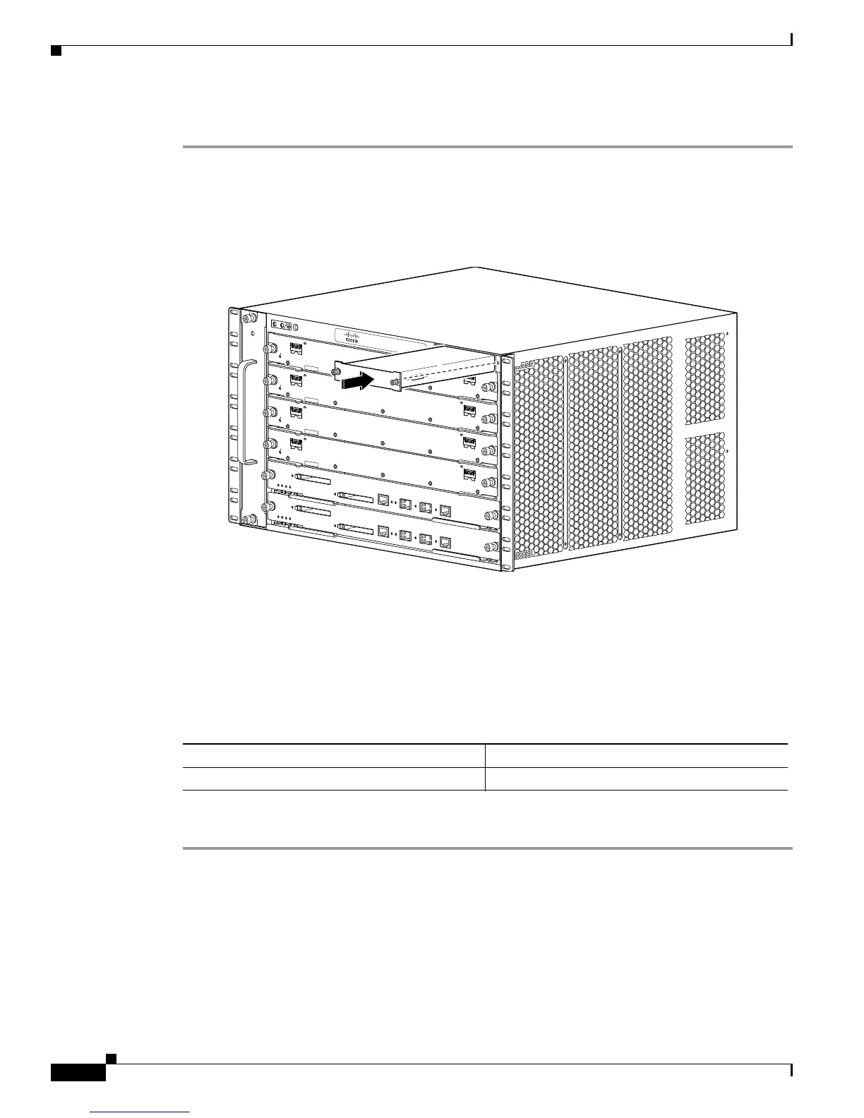
Step 1 Remove the thermistor module by unscrewing two captive thumbscrews (see Figure 5-132) and sliding
the termistor module out.
Step 2 Slide the replacement thermistor module into the chassis and tighten the two captive screws. the single
captive screw that retains the thermistor module in the chassis. See
Figure 5-132.
Figure 5-132 Thermistor Module Replacement.
Installing the Thermistor Module on a Cisco 7609-S Router
This section describes how to install the thermistor module for the Cisco 7609-S router. The necessary
parts can be ordered at listed in
Table 5-3.
Ta b l e 5-3 Thermistor Module Part Numbers
Perform these steps to replace a thermistor module.
Step 1 Remove the intake panel by unscrewing four captive thumbscrews (see Figure 5-133).
191925
S
T
A
T
U
S
C
is
c
o 7
60
6
FA
N
ST
AT U
S
1
2
3
4
5
6
A
/L
S
T
A
T
U
S
E
T
H
E
R
N
E
T
S
E
R
V
IC
E
S
M
O
D
U
L
E
7
6
0
0
-E
S
2
0
-
1
0
G
3
C
X
L
C
L
A
S
S
1
L
A
S
E
R
A/L
1
0
A
/L
S
T
A
T
U
S
E
T
H
E
R
N
E
T
S
E
R
V
IC
E
S
M
O
D
U
L
E
7
6
0
0
-E
S
2
0
-1
0
G
3
C
X
L
C
L
A
S
S
1
L
A
S
E
R
A
/L
1
0
A
/L
S
T
A
T
U
S
E
T
H
E
R
N
E
T
S
E
R
V
IC
E
S
M
O
D
U
L
E
7
6
0
0
-E
S
2
0
-1
0
G
3
C
X
L
C
L
A
S
S
1
L
A
S
E
R
A
/L
1
0
A
/L
S
T
A
T
U
S
E
T
H
E
R
N
E
T
S
E
R
V
IC
E
S
M
O
D
U
L
E
7
6
0
0
-
E
S
2
0
-
1
0
G
3
C
X
L
C
L
A
S
S
1
L
A
S
E
R
A
/L
1
0
THE
RM
-T
606S
Part Number Description
THERM-7609S= Replacement thermistor module