E-5
Cisco 7600 Series Router Installation Guide
OL-4503-26
Appendix E Cisco 7606-S DC Power Supply Configurations
Cisco 7606-S V02 Configuration with a 2700 W DC Power Supply and a 4500 W DC Power Supply
Step 7 Install the 4500 W DC in the lower slot as described in Installing a PWR-4500-DC Power Supply in a
Cisco 7606-S Router, page 5-61.
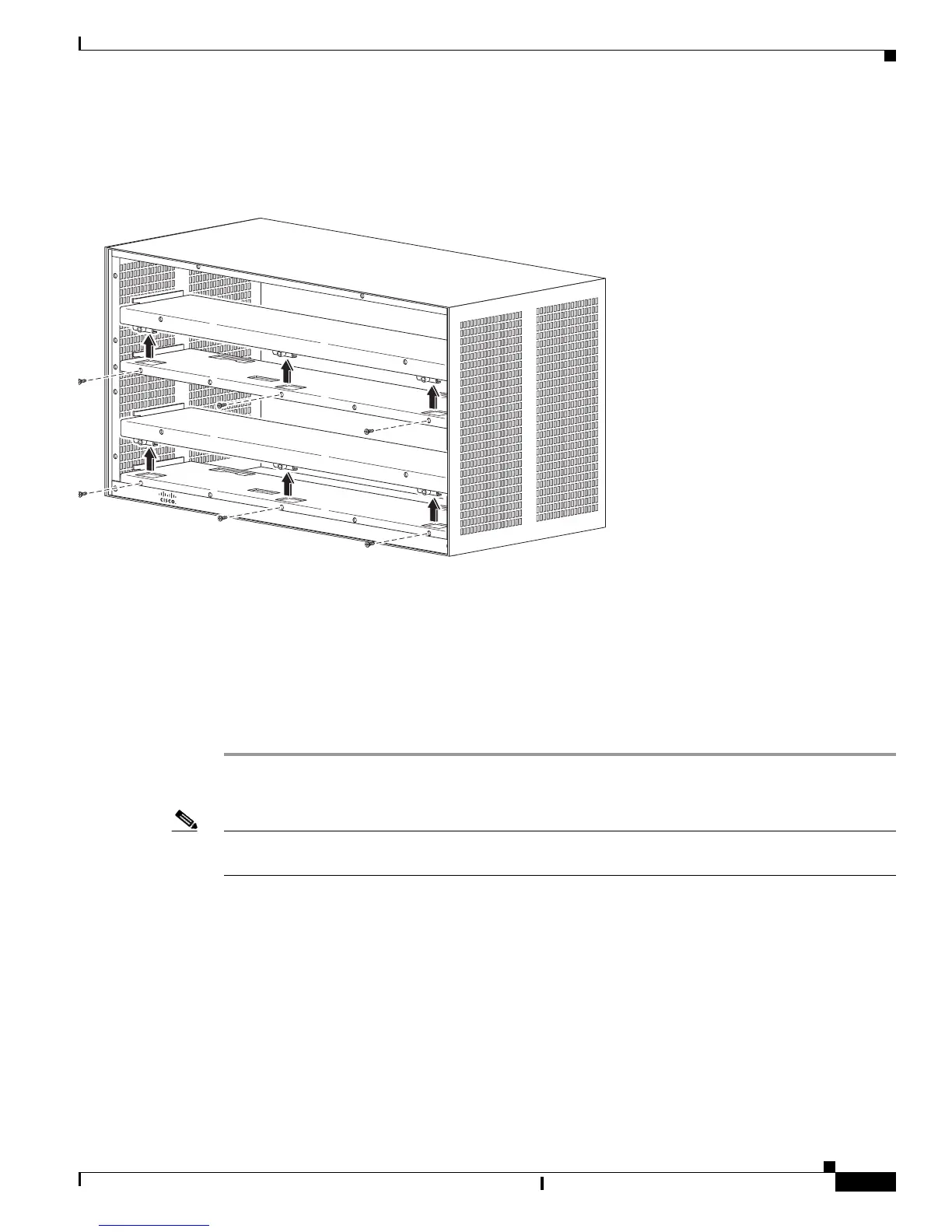
Figure E-4 Removing Booster Brackets
Cisco 7606-S V02 Configuration with a 2700 W DC Power Supply
and a 4500
W DC Power Supply
This configuration requires you to remove the lower booster bracket (Part Number 800-31261-01).
Step 1 Remove the PWR-2700-DC power supply from the lower slot as described in Removing PWR-2700-DC
Power Supply from a Cisco 7606-S Router, page 5-19.
Note When you are using a PWR-2700-DC and a PWR-4500-DC, you must install the PWR-4500-DC supply
in the lower slot.
Step 2 Remove three screws (Part Number 48-2454-01) securing the booster bracket (Part Number
800-31261-01) at the bottom slot See.
Figure E-4.
Step 3 Push the booster bracket (Part Number 800-31261-01) backward and then lift and remove it from the
chassis.
Step 4 Install the 4500 W DC in the lower slot as described in Installing a PWR-4500-DC Power Supply in a
Cisco 7606-S Router, page 5-61.