5-115
Cisco 7600 Series Router Installation Guide
OL-4503-26
Chapter 5 Removal and Replacement Procedures
Removing and Replacing the PEM
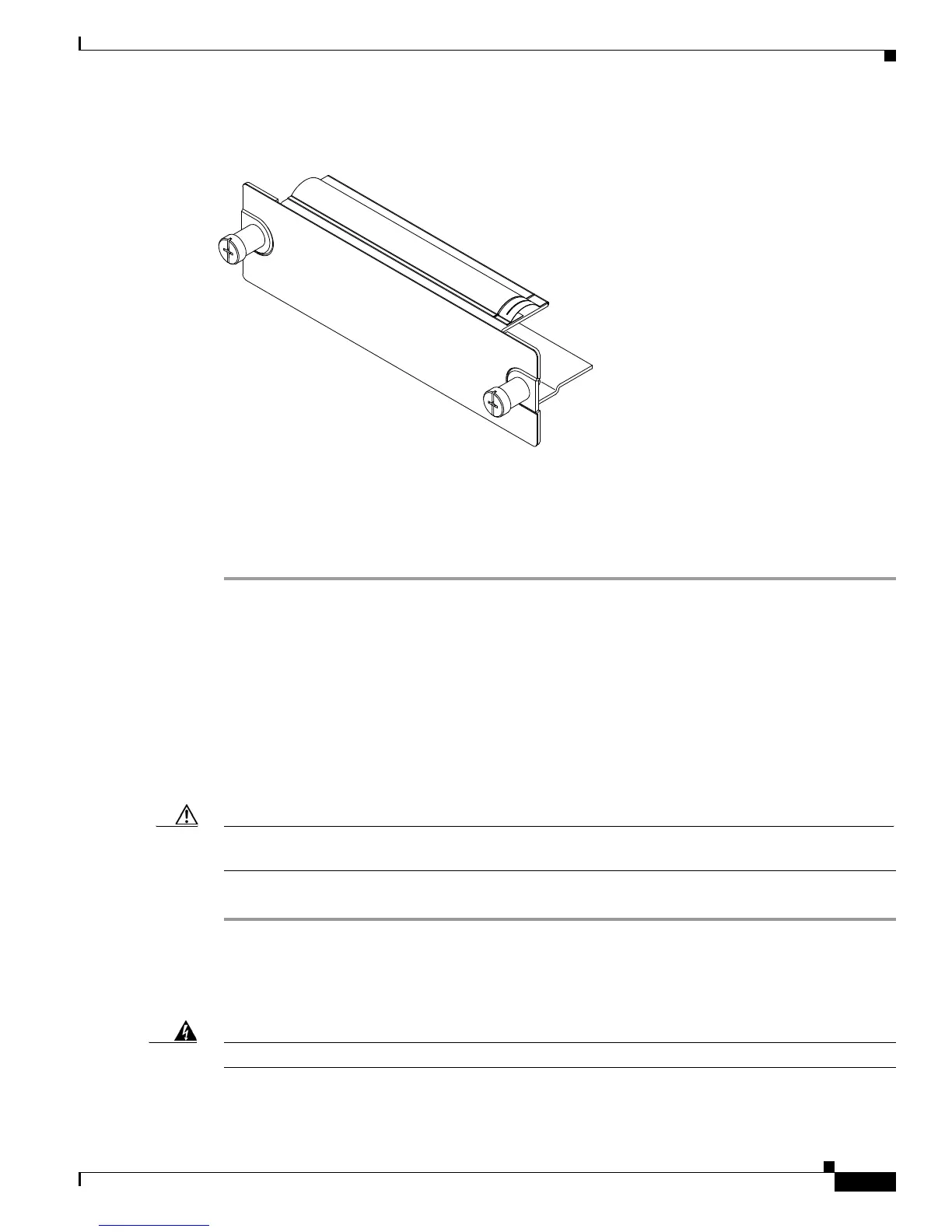
Figure 5-111 Blank PEM Filler Plate
Installing the AC-Input PEM
Follow these steps to install an AC-input PEM:
Step 1 Ensure that the system (earth) ground connection has been made. For ground connection instructions,
see the
“System Ground Connection” section on page 3-19.
Step 2 If necessary, remove the blank PEM filler plate (Cisco part number 800-16719-01) from the chassis PEM
bay opening by loosening the captive installation screws. See
Figure 5-111.
Step 3 Grasp the PEM with one hand. Place your other hand underneath the PEM, as shown in Figure 5-110.
Slide the PEM into the PEM bay. Make sure that the PEM is fully seated in the bay.
Step 4 Tighten the PEM captive installation screws (Figure 5-109).
Step 5 Plug the power cord into the PEM.
Step 6 Connect the other end of the power cord to an AC-input power source.
Caution In a system with dual power supplies, connect each power supply to a separate input source. In case of
a power source failure, the second source will most likely still be available.
Step 7 Turn the power switch to the On (|) position on the PEM.
Removing a DC-Input PEM
Warning
Before performing any of the following procedures, ensure that power is removed from the DC circuit.