E-3
Cisco 7600 Series Router Installation Guide
OL-4503-26
Appendix E Cisco 7606-S DC Power Supply Configurations
Cisco 7606-S V01 Configuration with a 2700 W DC Power Supply and a 4500 W DC Power Supply
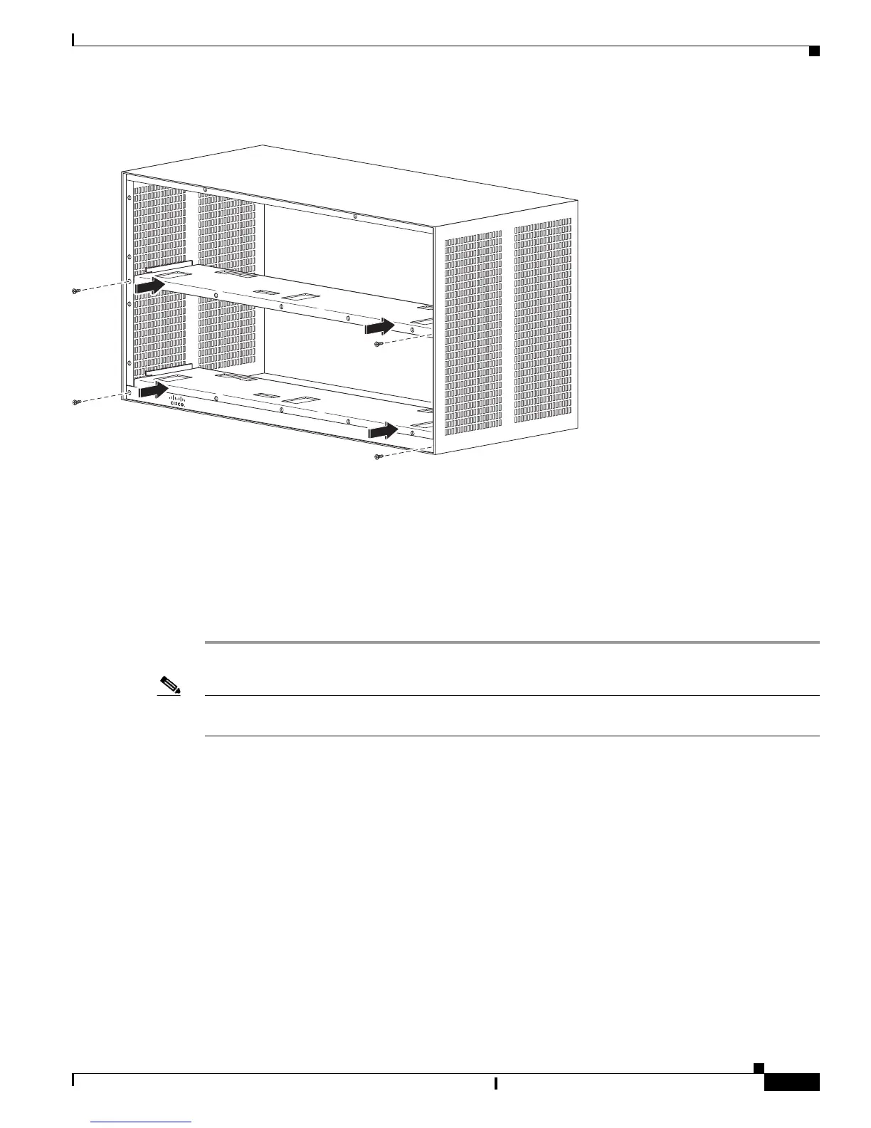
Figure E-2 Installing Slim Brackets
Cisco 7606-S V01 Configuration with a 2700 W DC Power Supply
and a 4500
W DC Power Supply
This configuration requires you to remove the booster brackets (Part Number 700-23386-01) and replace
them with the slim brackets (Part Number 700- 26979-01) . To do this, proceed as follows:
Step 1 Remove the power supplies as described in Removing a DC-Input Power Supply, page 5-9.
Note When you are using a PWR-2700-DC and a PWR-4500-DC, you must install the PWR-4500-DC supply
in the lower slot.
Step 2 Remove the two screws (Part Number 48-2030-01) securing the bracket (Part Number 700-23386-01) at
the top slot and remove the bracket. See
Figure E-1.
Step 3 Remove the two screws (Part Number 48-2030-01) securing the bracket (Part Number 700-23386-01) at
the lower slot and remove the bracket. See
Figure E-1.
Step 4 Use the screws (Part Number 48-2030-01) removed in Step 1 to install the slim bracket (Part Number
700-26979-01) at the top slot. See
Figure E-2.
Step 5 At the top slot, use three screws (Part Number 48-2454-01) to install the booster bracket (Part Number
800-31261-01) . See
Figure E-3.
Step 6 Install the 2700 W DC power supply in the top slot as described in Installing a PWR-2700-DC Power
Supply in a Cisco 7606-S Router, page 5-57.
Step 7 Install the 4500 W DC in the lower shelves as described in Installing a PWR-4500-DC Power Supply in
a Cisco 7606-S Router, page 5-61.
253052
Cisco 7600
Series