1-5
Cisco 7600 Series Router Installation Guide
OL-4503-26
Chapter 1 Product Overview
Cisco 7604 Router
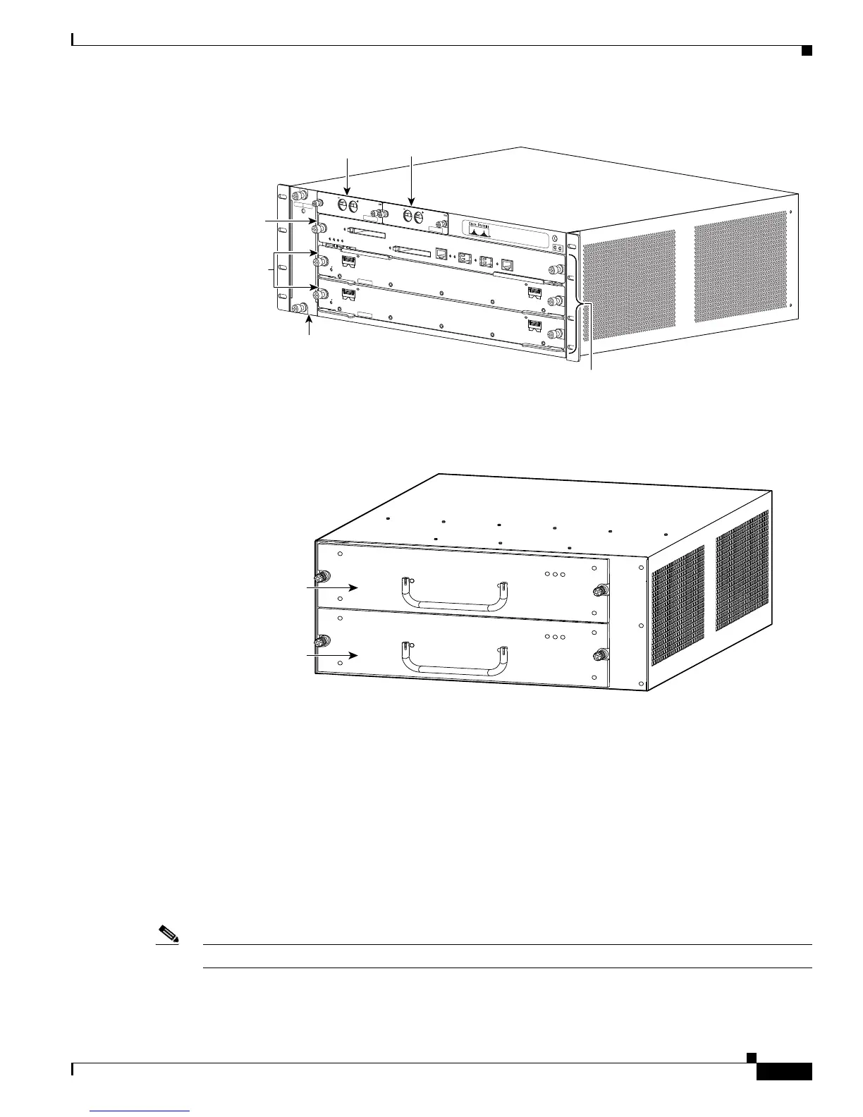
Figure 1-3 Cisco 7603-S Router—Front View
Figure 1-4 Cisco 7603-S Router—Rear View
Cisco 7604 Router
The Cisco 7604 router chassis has four horizontal slots that are numbered from top to bottom (See
Figure 1-5).
Slot 1 is reserved for the supervisor engine, which provides switching, local and remote management,
and multiple GBIC uplink ports.
Slot 2 can contain a redundant supervisor engine that can act as a backup if the first supervisor engine
fails. If a redundant supervisor engine is not required, slot 2 is available for an OSM or other supported
Catalyst 6500 series modules.
Note Both supervisor engines in a single chassis must be identical.
191810
FAN
STATUS
-4
8
T
O
-
6
0
V
5
0
A
M
A
X
P
E
M
-D
C
-
4
8
T
O
-6
0
V
5
0
A
M
A
X
P
E
M
-D
C
FAN -M
OD
-3SH
S
1
2
3
PEM
1
PEM
2
A/L
STATUS
E
T
H
E
R
N
E
T
S
E
R
V
IC
E
S
M
O
D
U
L
E
7
6
0
0
-E
S
2
0
-1
0
G
3
C
X
L
C
L
A
S
S
1
L
A
S
E
R
A/L
1
0
A/L
STATUS
E
T
H
E
R
N
E
T
S
E
R
V
IC
E
S
M
O
D
U
L
E
7
6
0
0
-E
S
2
0
-1
0
G
3
C
X
L
C
L
A
S
S
1
L
A
S
E
R
A/L
1
0
Slots 1-3
(top to bottom)
Fan assembly
Supervisor
Engine
Line Cards
PEM 1
PEM 2
63031
INPUT
OK
FAN
OK
OUTPUT
FAI L
INPUT
OK
FAN
OK
OUTPUT
FAI L
Power supply 2
(redundant)
Power supply 1