5-4
Cisco 7600 Series Router Installation Guide
OL-4503-26
Chapter 5 Removal and Replacement Procedures
Removing and Replacing the Power Supply
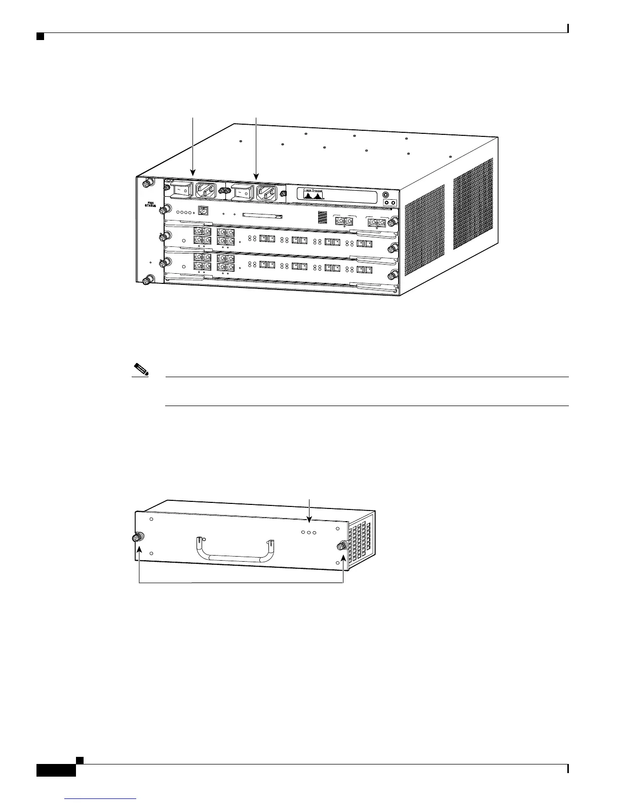
Figure 5-1 PEM Location
Step 2 Disconnect the power cord from the power source. Do not touch the metal prongs on the power cord
when it is still connected to the power supply or PEM.
Step 3 Remove the power cord from the power connection on the PEM. Do not touch the metal prongs
embedded in the PEM.
Note The AC power cord for the 4000 W power supply is hard-wired and cannot be removed from the
supply.
Step 4 Loosen the captive installation screws on the power supply. (See Figure 5-2 for the Cisco 7603 router,
Figure 5-3 for the Cisco 7604 router, Cisco 7606 router, andCisco 7606-S router, Figure 5-4 for the
Cisco 7609 router, Cisco 7609-S router, and Cisco 7613 router.)
Figure 5-2 Cisco 7603 Router—Power Supply Captive Installation Screws
S
U
P
E
R
V
IS
O
R
2
W
S
-X
6K
-S
U
P
2
-2
G
E
S
T
A
T
U
S
S
Y
S
T
E
M
C
O
N
S
O
L
E
P
W
R
M
G
M
T
R
E
S
E
T
C
O
NS
O
L
E
CO
N
S
O
LE
P
O
RT
M
O
D
E
PC
M
C
IA EJEC
T
PO
R
T
1
PO
R
T 2
Sw
itch
Lo
ad
100
%
1%
L
I
N
K
L
IN
K
O
S
M
-
4
O
C
1
2
P
O
S
-
S
I
4
P
O
R
T
O
C
-
1
2
P
O
S
S
M
IR
S
T
A
T
U
S
1
1
2
2
3
3
4
4
R
E
S
E
T
L
I
N
K
L
I
N
K
L
I
N
K
L
I
N
K
C
A
R
R
I
E
R
A
L
A
R
M
C
A
R
R
I
E
R
A
L
A
R
M
C
A
R
R
I
E
R
A
L
A
R
M
C
A
R
R
IE
R
A
L
A
R
M
A
C
T
I
V
E
T
X
R
X
T
X
P
O
R
T
1
R
X
A
C
T
I
V
E
T
X
R
X
T
X
P
O
R
T
2
R
X
A
C
T
I
V
E
T
X
R
X
T
X
P
O
R
T
3
R
X
A
C
T
IV
E
T
X
R
X
T
X
P
O
R
T
4
R
X
O
S
M
-4
O
C
1
2
P
O
S
-S
I
4
P
O
R
T
O
C
-
1
2
P
O
S
S
M
IR
S
T
A
T
U
S
1
1
2
2
3
3
4
4
R
E
S
E
T
L
IN
K
L
I
N
K
L
IN
K
L
I
N
K
C
A
R
R
I
E
R
A
L
A
R
M
C
A
R
R
IE
R
A
L
A
R
M
C
A
R
R
I
E
R
A
L
A
R
M
C
A
R
R
IE
R
A
L
A
R
M
A
C
T
I
V
E
T
X
R
X
T
X
P
O
R
T
1
R
X
A
C
T
I
V
E
T
X
R
X
T
X
P
O
R
T
2
R
X
A
C
T
I
V
E
T
X
R
X
T
X
P
O
R
T
3
R
X
A
C
T
I
V
E
T
X
R
X
T
X
P
O
R
T
4
R
X
63191
PEM 1 PEM 2
63183
IN
PUT
OK
FAN
O
K
O
UTP
UT
FAI L
Captive installation screws
Status LEDs