5-12
Cisco 7600 Series Router Installation Guide
OL-4503-26
Chapter 5 Removal and Replacement Procedures
Removing and Replacing the Power Supply
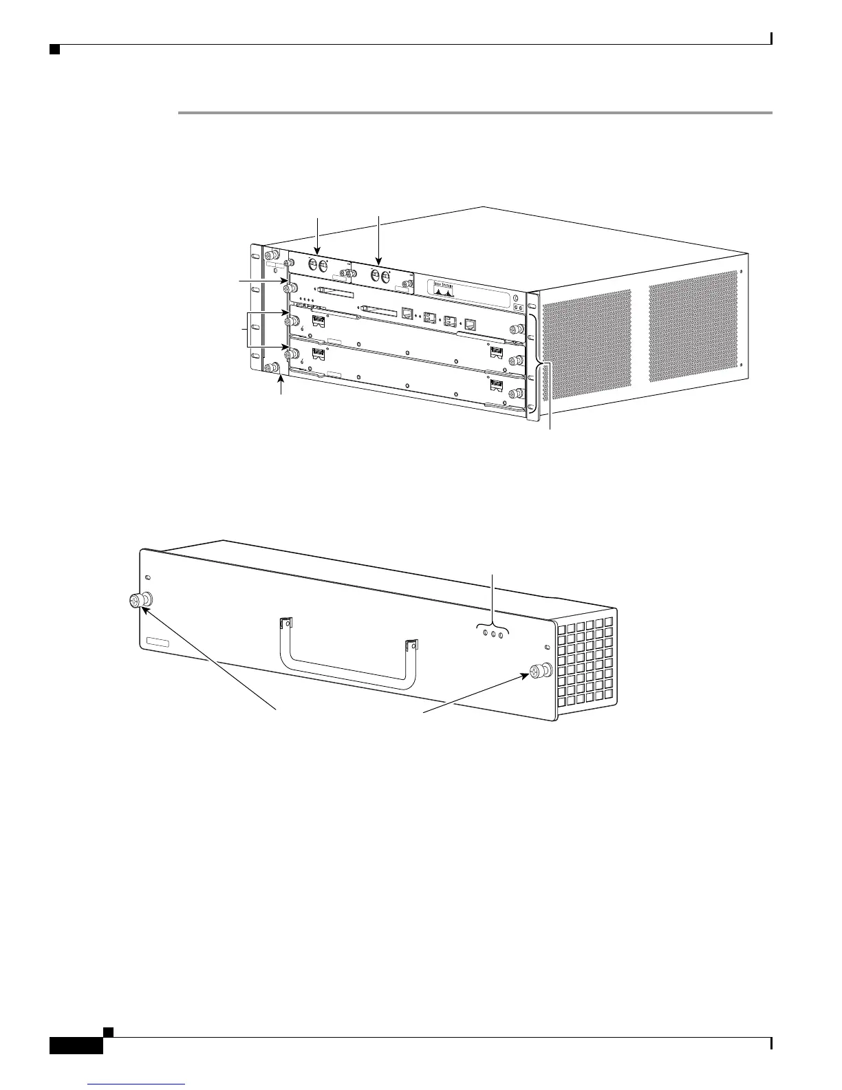
Step 1 Verify that power is off to the DC circuit connected to the DC PEM for the power supply you are
removing (
Figure 5-11).
Figure 5-11 PEM Locations
Step 2 Loosen the captive installation screws on the power supply (Figure 5-12).
Figure 5-12 Cisco 7603-S Router—Power Supply Captive Installation Screws
Step 3 Grasp the power supply handle, as shown in Figure 5-13, and slide the power supply completely out of
the chassis.
191810
FAN
STATUS
-48 TO -60V
50A
M
AX
PEM
-DC
-48
TO
-6
0V
5
0A M
AX
PEM-DC
FAN-MOD-3SHS
1
2
3
PEM 1
PEM 2
A/L
STA
TUS
ET
HERNET
SERVICES MO
DULE
7600-ES20-10G3CXL
CLASS 1 LASER
A/L
1
0
A/L
STA
TUS
ETHERNET
SERVICES MODULE
7600-ES20-10G3CXL
CLASS 1 LASER
A/L
1
0
Slots 1-3
(top to bottom)
Fan assembly
Supervisor
Engine
Line Cards
PEM 1
PEM 2
191812
PWR-1500-DC
INPUT OK
ALL FASTENERS MUST BE FULLY ENGAGED\
PRIOR TO OPERATING OF POWER SUPPY
FAN OK
OUTPUT FAIL
Captive installation screws
Status LEDs