5-20
Cisco 7600 Series Router Installation Guide
OL-4503-26
Chapter 5 Removal and Replacement Procedures
Removing and Replacing the Power Supply
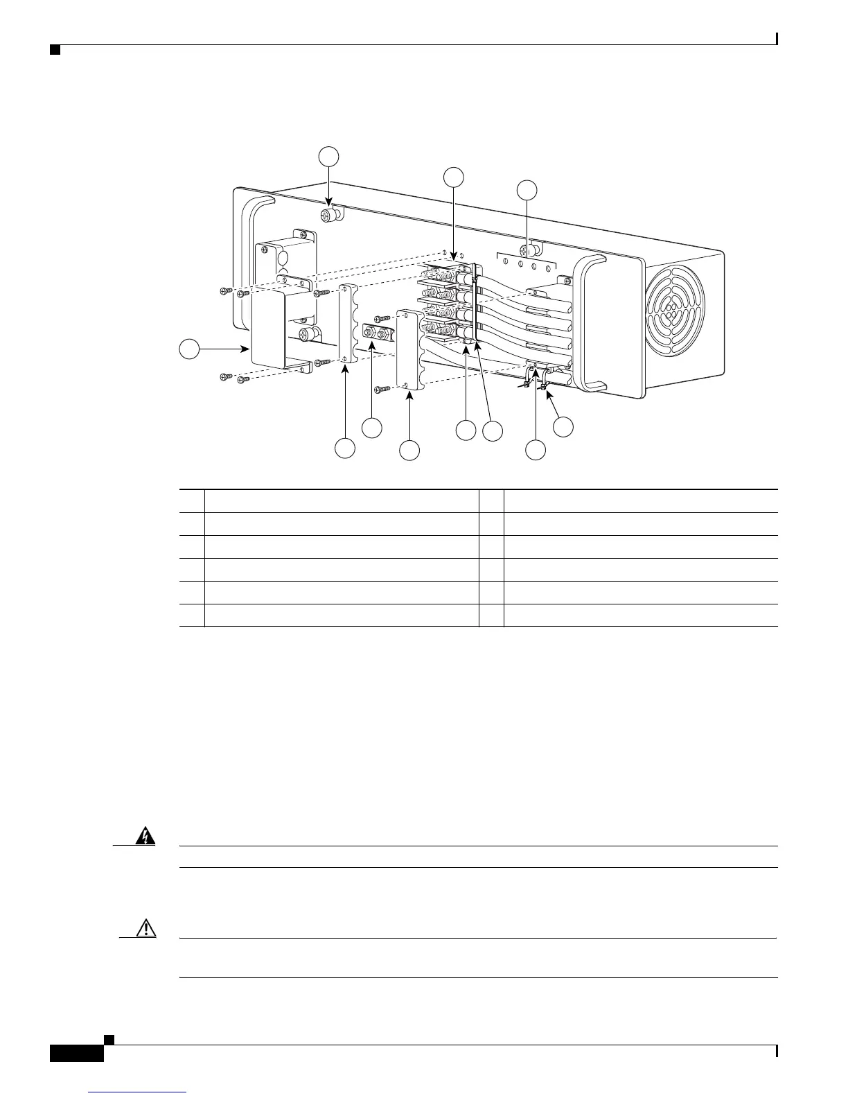
Figure 5-22 DC-Input Front Panel for 2700-W DC-Input Power Supply
Step 3 Remove the two screws securing each of the cable holder covers, and remove the cable holder covers off
the cable holders (
Figure 5-22).
Step 4 Disconnect the DC-input wires from the terminal block (Figure 5-22) in this order:
• Positive (+)
• Negative (-)
• Ground
Step 5 Remove the two tie-wraps from the ground cable. If there is a long cable tie securing the cable holders
as shown in
Figure 5-22, remove that as well.
Warning
When installing the unit, the ground connection must always be made first and disconnected last.
Step 6 Loosen the captive installation screws on the power supply (Figure 5-22).
Caution Use both hands to install and remove power supplies. Each PWR-2700-DC DC-input power supply
weighs 14.1 pounds (6.4 kg).
1 Captive installation screw 7 Cable holder cover
2 DC power cable terminal block 8 Cable holder
3 Status LEDs 9 Tie-wrap
4 DC power cable terminal block cover 10 Cable holder
5 Cable holder cover 11 Tie-wrap
6 Ground
119629
PWR-2700-DC/6
-VE-1
-VE-1
-VE-2
-VE-2
IN
PU
T1
O
K
48
V-60V
=
40A
INP
U
T2
O
K
48
V-60V
=
40A
FA
N
OK
O
U
TP
U
T
FA
IL
ALL FASTENER
S MU
ST BE FULLY ENGA
GED
PRIOR TO OPERATING
TH
E POW
ER SUPPLY
3
2
6
4
10
1
8
5
7
11
9