5-39
Cisco 7600 Series Router Installation Guide
OL-4503-26
Chapter 5 Removal and Replacement Procedures
Removing and Replacing the Power Supply
Step 1 Verify that power is off to the DC circuit connected to the DC-input power supply you are removing.
Step 2 Turn the power switch to the Off (0) position on the power supply you are removing (Figure 5-43).
Turning the power switch off also disengages a pawl that unlocks the power supply from the chassis.
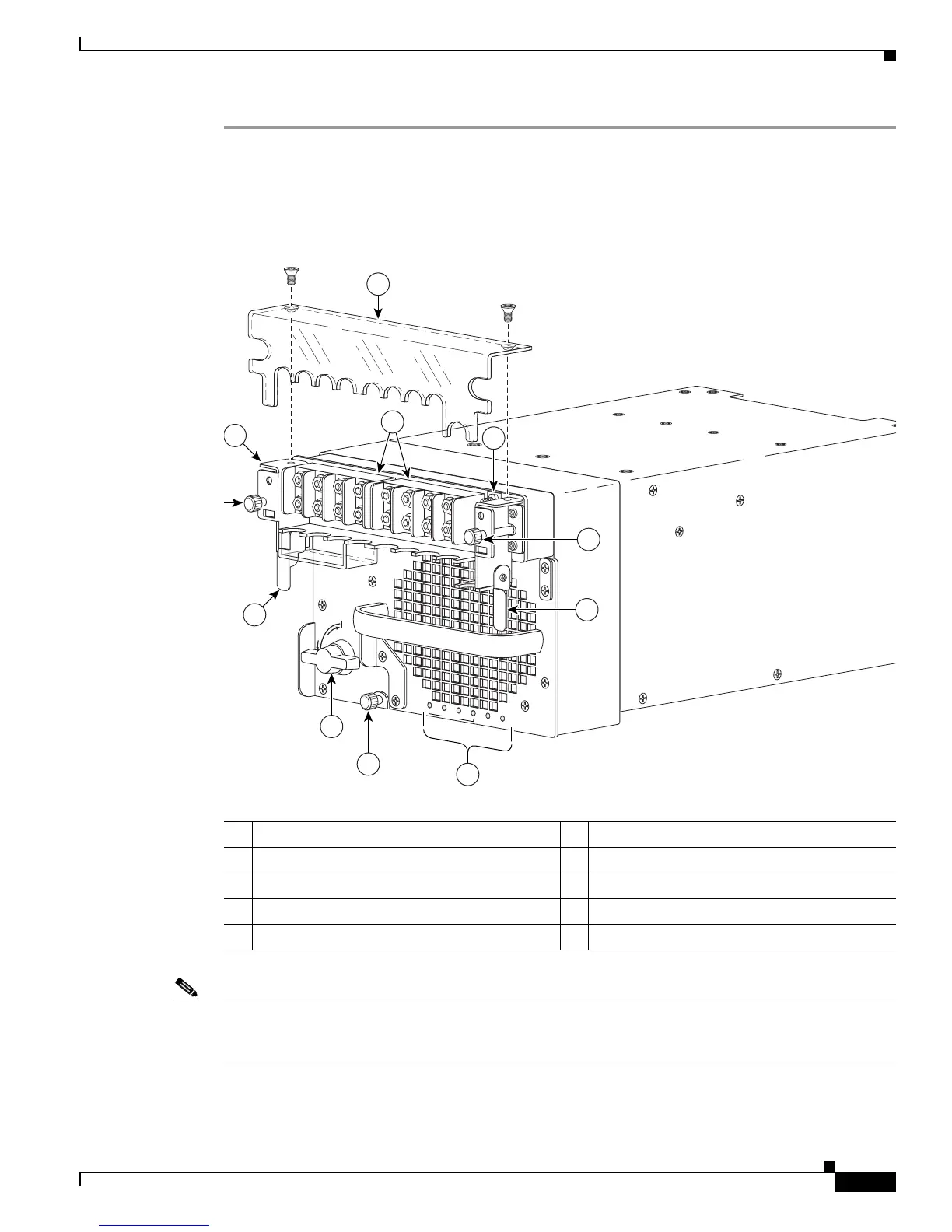
Figure 5-43 DC-Input Front Panel for 6000-W DC-Input Power Supply
Note With the PWR-6000-DC power supply, you have the option of removing the Input Power Module (IPM)
without disconnecting the DC-input wires and the ground wires. You can then replace your power supply
and insert the fully-wired IPM. To use this option, do not perform steps 3 through 6 and go to step 7.
Step 3 Remove the two A4 screws securing the terminal block cover, and remove the cover from the power
supply (
Figure 5-43).
1 Terminal block cover 6 Captive installation screw
2 DC power cable terminal block 7 Input Power Module (IPM)
3 Ground 8 IPM captive screws
4 Status LEDs 9 IPM latches
5 Power switch
R
U
N
I
N
S
T
A
L
L
CISCO SYSTEMS, INC
1
2
3
4
INPUT OK
FAN
OK
OUTPUT
FAIL
1
2
3
4
5
6
7
9
9
8