5-102
Cisco 7600 Series Router Installation Guide
OL-4503-26
Chapter 5 Removal and Replacement Procedures
Removing and Replacing the Power Supply
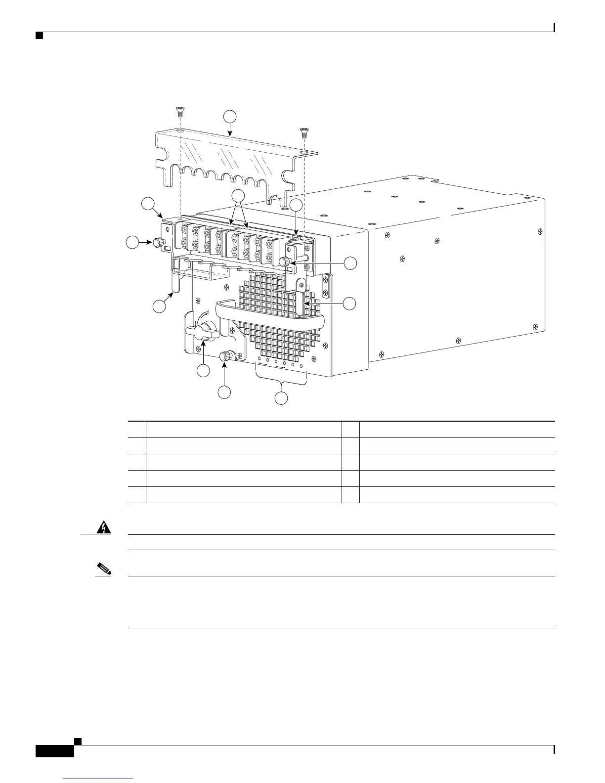
Figure 5-97 6000 W DC-Input Power Supply Front Panel
Warning
Power supply captive installation screws must be tight to ensure protective grounding continuity.
Note With the PWR-6000-DC power supply, you have the option of installing an Input Power Module (IPM)
(previously removed) with the DC-input wires and the ground wires still connected. You can then install
your power supply and insert the fully-wired IPM. If you are going to install an IPM with DC-input wires
and ground wires still connected, skip steps 4 through 12 and go directly to step 13.
Step 4 Remove the two A4 screws securing the outer terminal block cover, and remove the cover from the power
supply (
Figure 5-97).
Step 5 Attach the appropriate lugs to the DC-input wires and ground wire. The wires should be sized according
to local and national installation requirements. Use only copper wire.
1 Terminal block cover 6 Captive installation screw
2 DC power cable terminal block 7 Input Power Module (IPM)
3 Ground 8 IPM captive screws
4 Status LEDs 9 IPM latches
5 Power switch
191286
R
U
N
I
N
S
T
A
L
L
CISCO SYSTEMS, INC
1
2
3
4
IN
P
U
T
O
K
FA
N
O
K
O
U
T
P
U
T
F
A
IL
1
2
3
4
5
6
7
8
9
9
8