1-33
Cisco 7600 Series Router Installation Guide
OL-4503-26
Chapter 1 Product Overview
Cisco 7600 Series Router Components
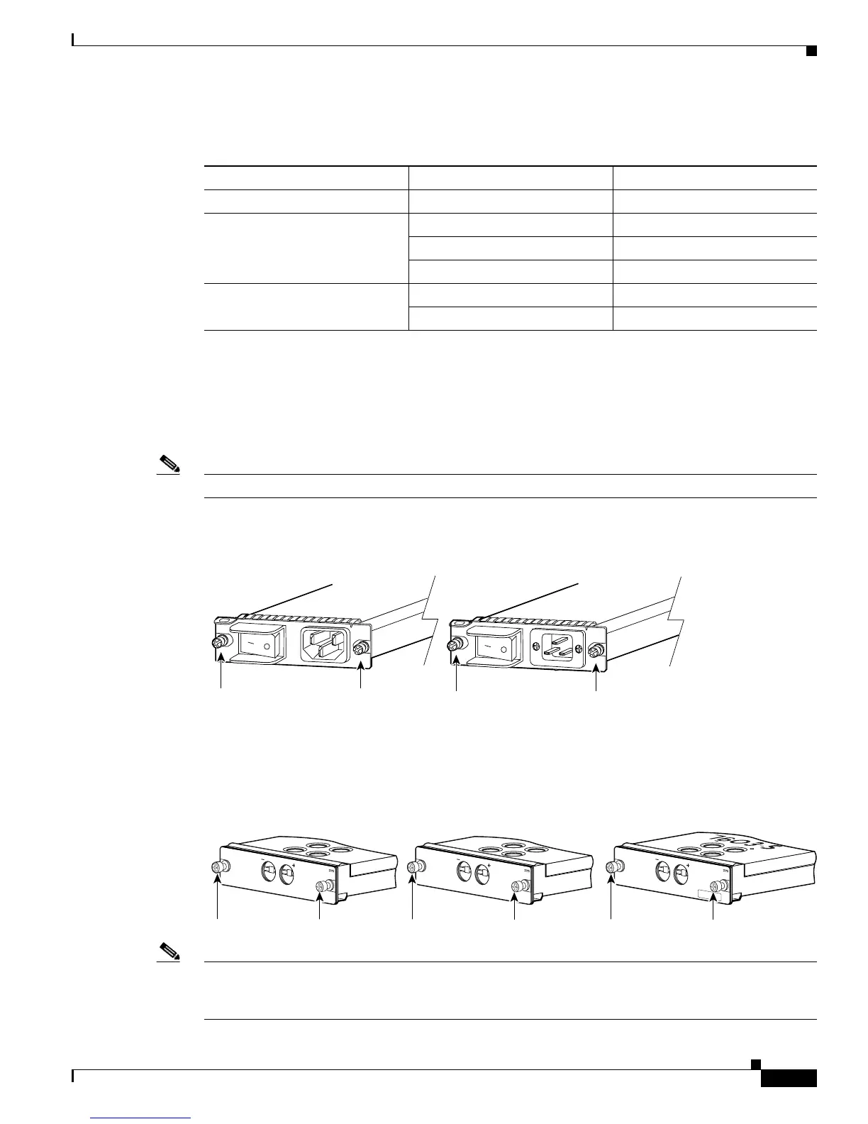
The AC-input PEMs (shown in Figure 1-34) and DC-input PEMs (shown in Figure 1-35) provide an
input power connection on the front of the router chassis to connect the site power source to the power
supply.
The PEMs have a power switch (AC-input only), current protection, surge and EMI suppression, and
filtering functions.
Note The top of the PEM is labeled either “7603” or “7603-S” or“7606”.
Figure 1-34 AC-Input PEMs
Figure 1-35 DC-Input PEMs
Note Figure 1-36 shows the location of the AC-input PEMs on the Cisco 7603 Internet Router. The location
of the PEMs is the same for AC and DC PEMs on the Cisco 7603 router, Cisco 7603-S router, and Cisco
7606 router.
Ta b l e 1-3 Power Supplies and PEMs
Cisco 7600 Router Power Supply PEM
Cisco 7603-S router PWR-1500-DC PEM-1500W-DC/03S
Cisco 7603 router PWR-950-AC PEM-15A-AC
PWR-950-DC PEM-DC/3
PWR-1400-AC PEM-20A-AC+
Cisco 7606 router PWR-1900-AC/6 PEM-20A-AC
PWR-1900-DC PEM-DC
Captive installation screws
63912
Captive installation screws
Cisco 7603 Internet Router AC PEM Cisco 7606 Internet Router AC PEM
Captive installation screws
191813
-48 TO -60V
50A MAX
PEM-DC
-48 TO -60V
50A MAX
PEM-DC
-48 TO -60V
25A MAX
PEM-DC/3
Captive installation screws
Captive installation screws
Cisco 7603 Router DC PEM
Cisco 7606 Router DC PEM Cisco 7603-S Router DC PEM