◦
Selects the lowest root bridge ID
◦
Selects the lowest path cost to the root switch
◦
Selects the lowest designated bridge ID
◦
Selects the lowest designated path cost
◦
Selects the lowest port ID
•
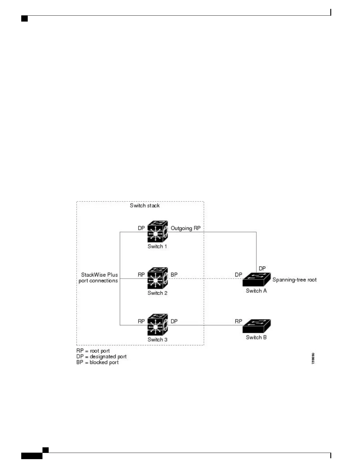
Only one outgoing port on the stack root switch is selected as the root port. The remaining switches in
the stack become its designated switches (Switch 2 and Switch 3) as shown in the following figure.
•
The shortest distance to the root switch is calculated for each switch based on the path cost.
•
A designated switch for each LAN segment is selected. The designated switch incurs the lowest path
cost when forwarding packets from that LAN to the root switch. The port through which the designated
switch is attached to the LAN is called the designated port.
One stack member is elected as the stack root switch. The stack root switch contains the outgoing root port
(Switch 1).
Figure 1: Spanning-Tree Port States in a Switch Stack
All paths that are not needed to reach the root switch from anywhere in the switched network are placed in
the spanning-tree blocking mode.
Related Topics
Configuring the Root Switch, on page 29
Catalyst 2960-XR Switch Layer 2 Configuration Guide, Cisco IOS Release 15.0(2)EX1
16 OL-29424-01
Configuring Spanning Tree Protocol
Spanning Tree Protocol

 Loading...