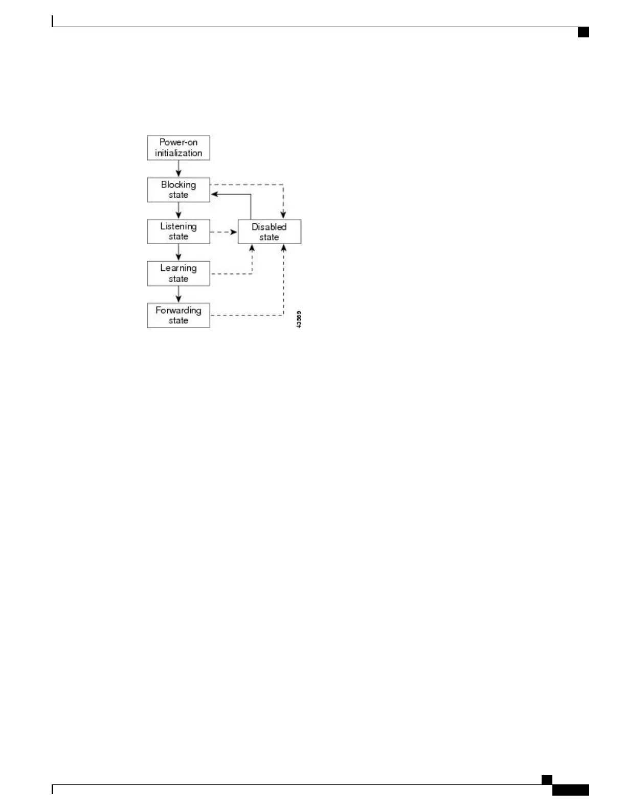
An interface moves through the states.
Figure 2: Spanning-Tree Interface States
When you power up the switch, spanning tree is enabled by default, and every interface in the switch, VLAN,
or network goes through the blocking state and the transitory states of listening and learning. Spanning tree
stabilizes each interface at the forwarding or blocking state.
When the spanning-tree algorithm places a Layer 2 interface in the forwarding state, this process occurs:
1
The interface is in the listening state while spanning tree waits for protocol information to move the
interface to the blocking state.
2
While spanning tree waits for the forward-delay timer to expire, it moves the interface to the learning state
and resets the forward-delay timer.
3
In the learning state, the interface continues to block frame forwarding as the switch learns end-station
location information for the forwarding database.
4
When the forward-delay timer expires, spanning tree moves the interface to the forwarding state, where
both learning and frame forwarding are enabled.
Blocking State
A Layer 2 interface in the blocking state does not participate in frame forwarding. After initialization, a BPDU
is sent to each switch interface. A switch initially functions as the root until it exchanges BPDUs with other
switches. This exchange establishes which switch in the network is the root or root switch. If there is only
one switch in the network, no exchange occurs, the forward-delay timer expires, and the interface moves to
the listening state. An interface always enters the blocking state after switch initialization.
An interface in the blocking state performs these functions:
•
Discards frames received on the interface
•
Discards frames switched from another interface for forwarding
•
Does not learn addresses
•
Receives BPDUs
Catalyst 2960-XR Switch Layer 2 Configuration Guide, Cisco IOS Release 15.0(2)EX1
OL-29424-01 19
Configuring Spanning Tree Protocol
Spanning Tree Protocol

 Loading...