MSTP Configuration Guidelines
These are the configuration guidelines for MSTP:
•
When you enable MST by using the spanning-tree mode mst global configuration command, RSTP
is automatically enabled.
•
For configuration guidelines about UplinkFast, BackboneFast, and cross-stack UplinkFast, see the
relevant sections in the Related Topics section.
•
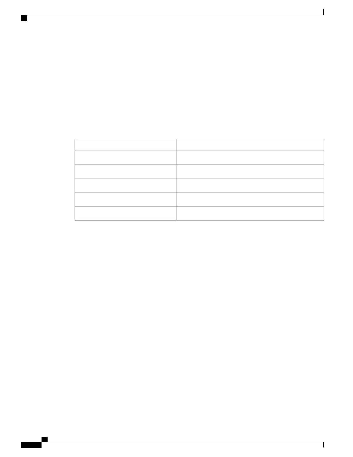
When the switch is in MST mode, it uses the long path-cost calculation method (32 bits) to compute the
path cost values. With the long path-cost calculation method, the following path cost values are supported:
Path Cost ValueSpeed
2,000,00010 Mb/s
200,000100 Mb/s
20,0001 Gb/s
2,00010 Gb/s
200100 Gb/s
Related Topics
Specifying the MST Region Configuration and Enabling MSTP, on page 59
Prerequisites for MSTP, on page 41
Restrictions for MSTP, on page 42
Spanning-Tree Interoperability and Backward Compatibility, on page 24
Optional Spanning-Tree Configuration Guidelines
BackboneFast, on page 86
UplinkFast, on page 82
Root Switch
The switch maintains a spanning-tree instance for the group of VLANs mapped to it. A switch ID, consisting
of the switch priority and the switch MAC address, is associated with each instance. For a group of VLANs,
the switch with the lowest switch ID becomes the root switch.
When you configure a switch as the root, you modify the switch priority from the default value (32768) to a
significantly lower value so that the switch becomes the root switch for the specified spanning-tree instance.
When you enter this command, the switch checks the switch priorities of the root switches. Because of the
extended system ID support, the switch sets its own priority for the specified instance to 24576 if this value
will cause this switches to become the root for the specified spanning-tree instance.
Catalyst 2960-XR Switch Layer 2 Configuration Guide, Cisco IOS Release 15.0(2)EX1
44 OL-29424-01
Configuring Multiple Spanning-Tree Protocol
MSTP Configuration Guidelines

 Loading...