Spanning-Tree Interoperability and Backward Compatibility
In a mixed MSTP and PVST+ network, the common spanning-tree (CST) root must be inside the MST
backbone, and a PVST+ switch cannot connect to multiple MST regions.
When a network contains switches running Rapid PVST+ and switches running PVST+, we recommend that
the Rapid PVST+ switches and PVST+ switches be configured for different spanning-tree instances. In the
Rapid PVST+ spanning-tree instances, the root switch must be a Rapid PVST+ switch. In the PVST+ instances,
the root switch must be a PVST+ switch. The PVST+ switches should be at the edge of the network.
All stack members run the same version of spanning tree (all PVST+, all Rapid PVST+, or all MSTP).
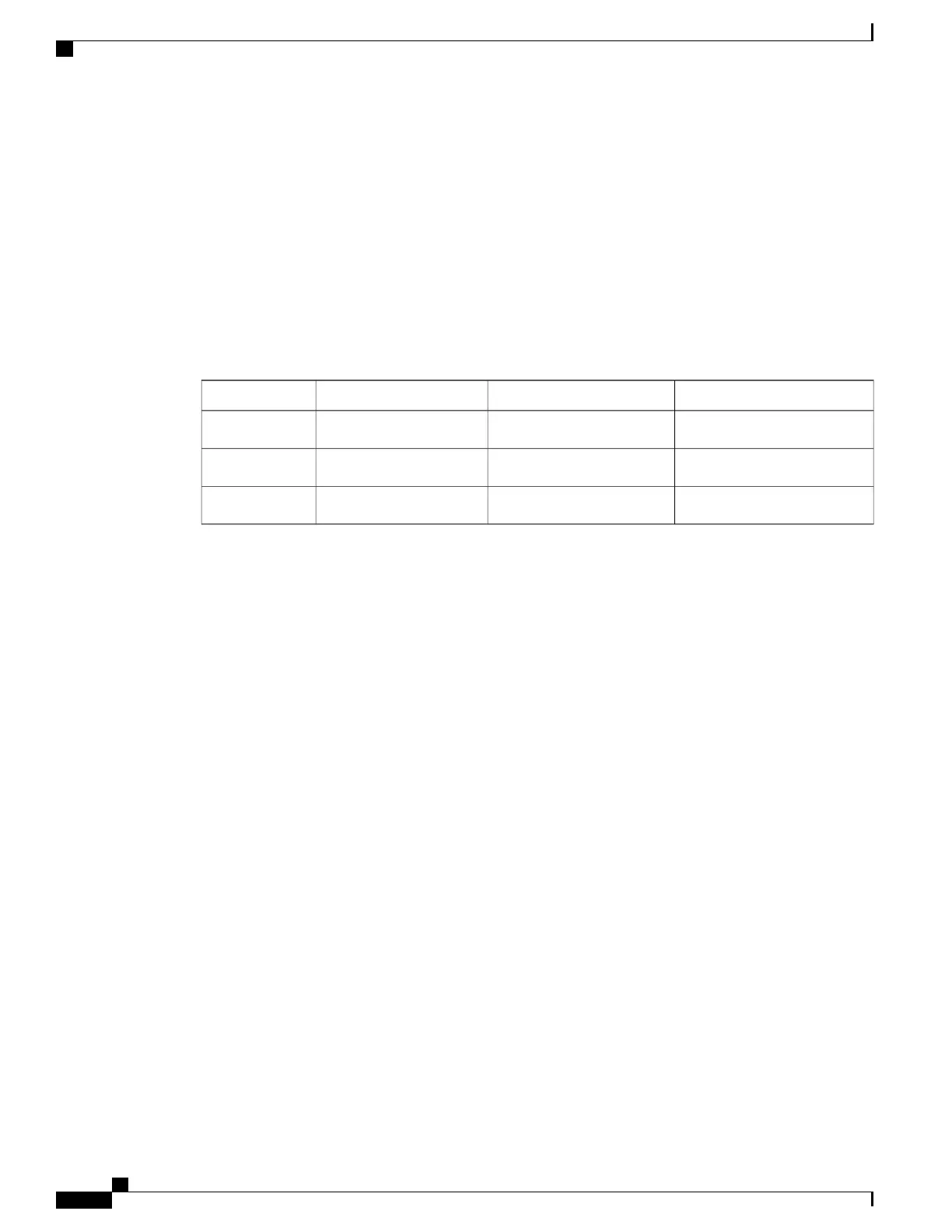
Table 5: PVST+, MSTP, and Rapid-PVST+ Interoperability and Compatibility
Rapid PVST+MSTPPVST+
Yes (reverts to PVST+)Yes (with restrictions)YesPVST+
Yes (reverts to PVST+)YesYes (with restrictions)MSTP
YesYes (reverts to PVST+)Yes (reverts to PVST+)Rapid PVST+
Related Topics
Specifying the MST Region Configuration and Enabling MSTP, on page 59
MSTP Configuration Guidelines, on page 44
Multiple Spanning-Tree Regions, on page 45
STP and IEEE 802.1Q Trunks
The IEEE 802.1Q standard for VLAN trunks imposes some limitations on the spanning-tree strategy for a
network. The standard requires only one spanning-tree instance for all VLANs allowed on the trunks. However,
in a network of Cisco switches connected through IEEE 802.1Q trunks, the switches maintain one spanning-tree
instance for each VLAN allowed on the trunks.
When you connect a Cisco switch to a non-Cisco device through an IEEE 802.1Q trunk, the Cisco switch
uses PVST+ to provide spanning-tree interoperability. If Rapid PVST+ is enabled, the switch uses it instead
of PVST+. The switch combines the spanning-tree instance of the IEEE 802.1Q VLAN of the trunk with the
spanning-tree instance of the non-Cisco IEEE 802.1Q switch.
However, all PVST+ or Rapid PVST+ information is maintained by Cisco switches separated by a cloud of
non-Cisco IEEE 802.1Q switches. The non-Cisco IEEE 802.1Q cloud separating the Cisco switches is treated
as a single trunk link between the switches.
PVST+ is automatically enabled on IEEE 802.1Q trunks, and no user configuration is required. The external
spanning-tree behavior on access ports and Inter-Switch Link (ISL) trunk ports is not affected by PVST+.
VLAN-Bridge Spanning Tree
Cisco VLAN-bridge spanning tree is used with the fallback bridging feature (bridge groups), which forwards
non-IP protocols such as DECnet between two or more VLAN bridge domains or routed ports. The
Catalyst 2960-XR Switch Layer 2 Configuration Guide, Cisco IOS Release 15.0(2)EX1
24 OL-29424-01
Configuring Spanning Tree Protocol
Spanning Tree Protocol

 Loading...