•
Does not receive BPDUs
How a Switch or Port Becomes the Root Switch or Root Port
If all switches in a network are enabled with default spanning-tree settings, the switch with the lowest MAC
address becomes the root switch.
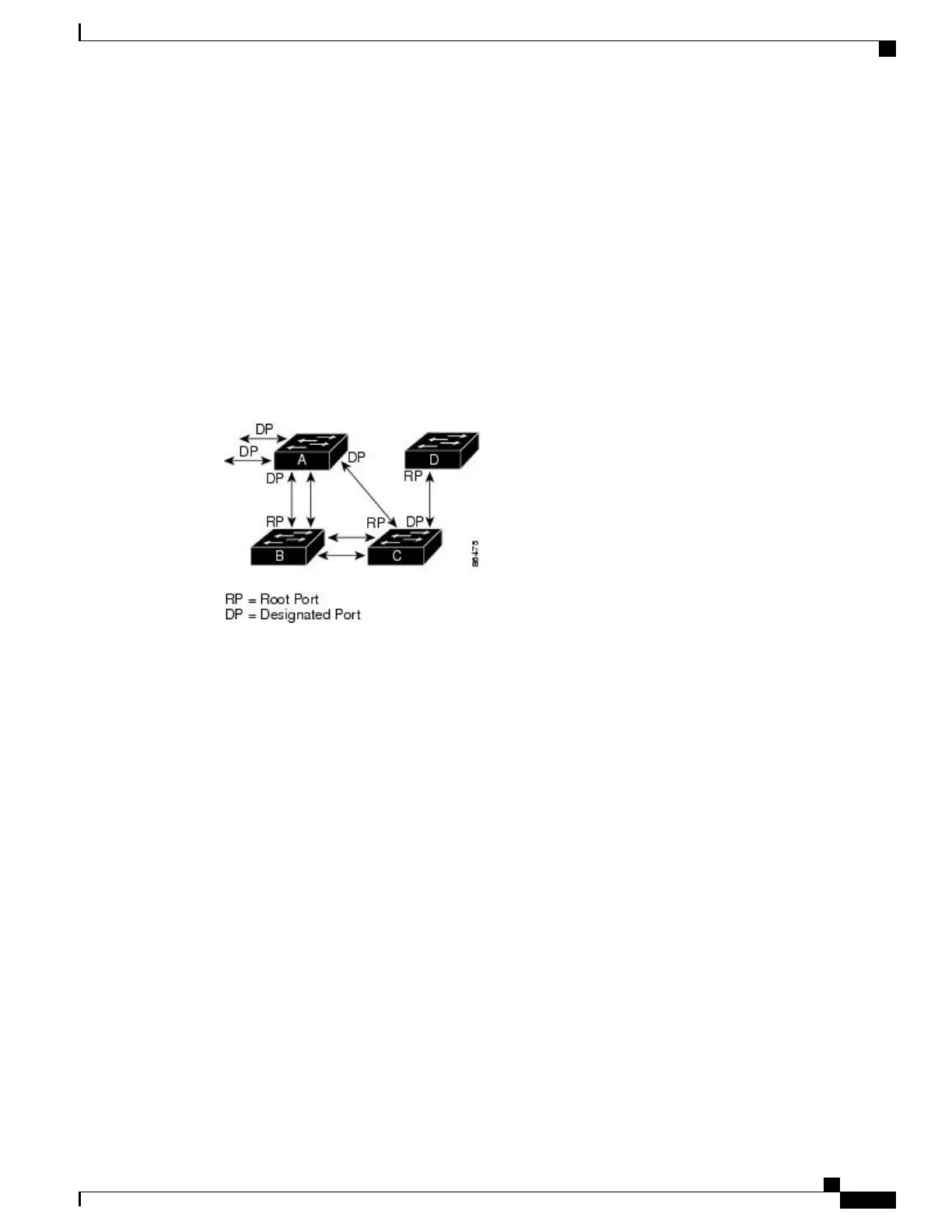
Switch A is elected as the root switch because the switch priority of all the switches is set to the default (32768)
and Switch A has the lowest MAC address. However, because of traffic patterns, number of forwarding
interfaces, or link types, Switch A might not be the ideal root switch. By increasing the priority (lowering the
numerical value) of the ideal switch so that it becomes the root switch, you force a spanning-tree recalculation
to form a new topology with the ideal switch as the root.
Figure 3: Spanning-Tree Topology
When the spanning-tree topology is calculated based on default parameters, the path between source and
destination end stations in a switched network might not be ideal. For instance, connecting higher-speed links
to an interface that has a higher number than the root port can cause a root-port change. The goal is to make
the fastest link the root port.
For example, assume that one port on Switch B is a Gigabit Ethernet link and that another port on Switch B
(a 10/100 link) is the root port. Network traffic might be more efficient over the Gigabit Ethernet link. By
changing the spanning-tree port priority on the Gigabit Ethernet port to a higher priority (lower numerical
value) than the root port, the Gigabit Ethernet port becomes the new root port.
Related Topics
Configuring Port Priority, on page 31
Spanning Tree and Redundant Connectivity
You can create a redundant backbone with spanning tree by connecting two switch interfaces to another device
or to two different devices. Spanning tree automatically disables one interface but enables it if the other one
fails. If one link is high-speed and the other is low-speed, the low-speed link is always disabled. If the speeds
Catalyst 2960-XR Switch Layer 2 Configuration Guide, Cisco IOS Release 15.0(2)EX1
OL-29424-01 21
Configuring Spanning Tree Protocol
Spanning Tree Protocol

 Loading...