Restrictions for STP, on page 13
Bridge ID, Device Priority, and Extended System ID
The IEEE 802.1D standard requires that each switch has an unique bridge identifier (bridge ID), which controls
the selection of the root switch. Because each VLAN is considered as a different logical bridge with PVST+
and Rapid PVST+, the same switch must have a different bridge ID for each configured VLAN. Each VLAN
on the switch has a unique 8-byte bridge ID. The 2 most-significant bytes are used for the switch priority, and
the remaining 6 bytes are derived from the switch MAC address.
The switch supports the IEEE 802.1t spanning-tree extensions, and some of the bits previously used for the
switch priority are now used as the VLAN identifier. The result is that fewer MAC addresses are reserved for
the switch, and a larger range of VLAN IDs can be supported, all while maintaining the uniqueness of the
bridge ID.
The 2 bytes previously used for the switch priority are reallocated into a 4-bit priority value and a 12-bit
extended system ID value equal to the VLAN ID.
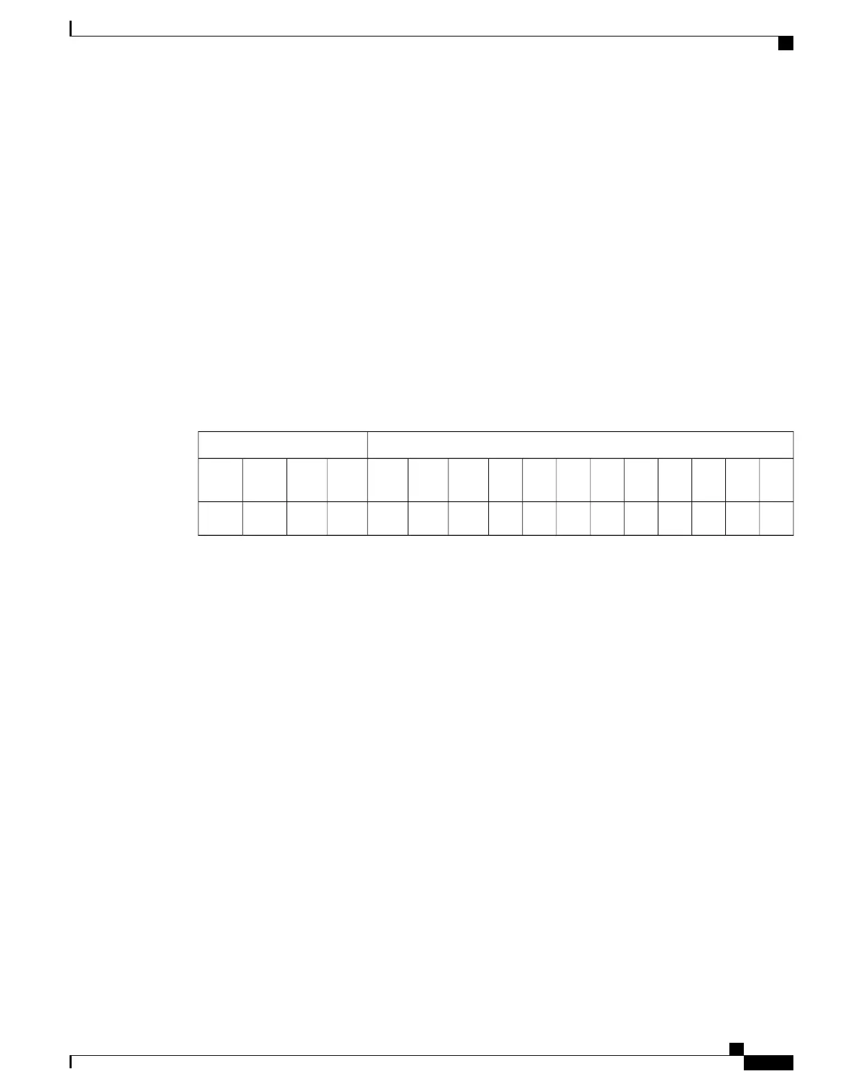
Table 4: Device Priority Value and Extended System ID
Extended System ID (Set Equal to the VLAN ID)Priority Value
Bit
1
Bit
2
Bit
3
Bit
4
Bit
5
Bit
6
Bit
7
Bit
8
Bit
9
Bit 10Bit 11Bit 12Bit 13Bit 14Bit 15Bit 16
124816326412825651210242048409681921638432768
Spanning tree uses the extended system ID, the switch priority, and the allocated spanning-tree MAC address
to make the bridge ID unique for each VLAN. Because the switch stack appears as a single switch to the rest
of the network, all switches in the stack use the same bridge ID for a given spanning tree. If the stack master
fails, the stack members recalculate their bridge IDs of all running spanning trees based on the new MAC
address of the new stack master.
Support for the extended system ID affects how you manually configure the root switch, the secondary root
switch, and the switch priority of a VLAN. For example, when you change the switch priority value, you
change the probability that the switch will be elected as the root switch. Configuring a higher value decreases
the probability; a lower value increases the probability.
If any root switch for the specified VLAN has a switch priority lower than 24576, the switch sets its own
priority for the specified VLAN to 4096 less than the lowest switch priority. 4096 is the value of the
least-significant bit of a 4-bit switch priority value as shown in the table.
Related Topics
Configuring the Root Switch, on page 29
Restrictions for STP, on page 13
Configuring the Root Switch, on page 62
Root Switch, on page 44
Specifying the MST Region Configuration and Enabling MSTP, on page 59
Catalyst 2960-XR Switch Layer 2 Configuration Guide, Cisco IOS Release 15.0(2)EX1
OL-29424-01 17
Configuring Spanning Tree Protocol
Spanning Tree Protocol

 Loading...