3-25
Catalyst 4500 Series Switches Installation Guide
78-14409-08
Chapter 3 Installing the Switch in a Rack
System Ground Connection Guidelines
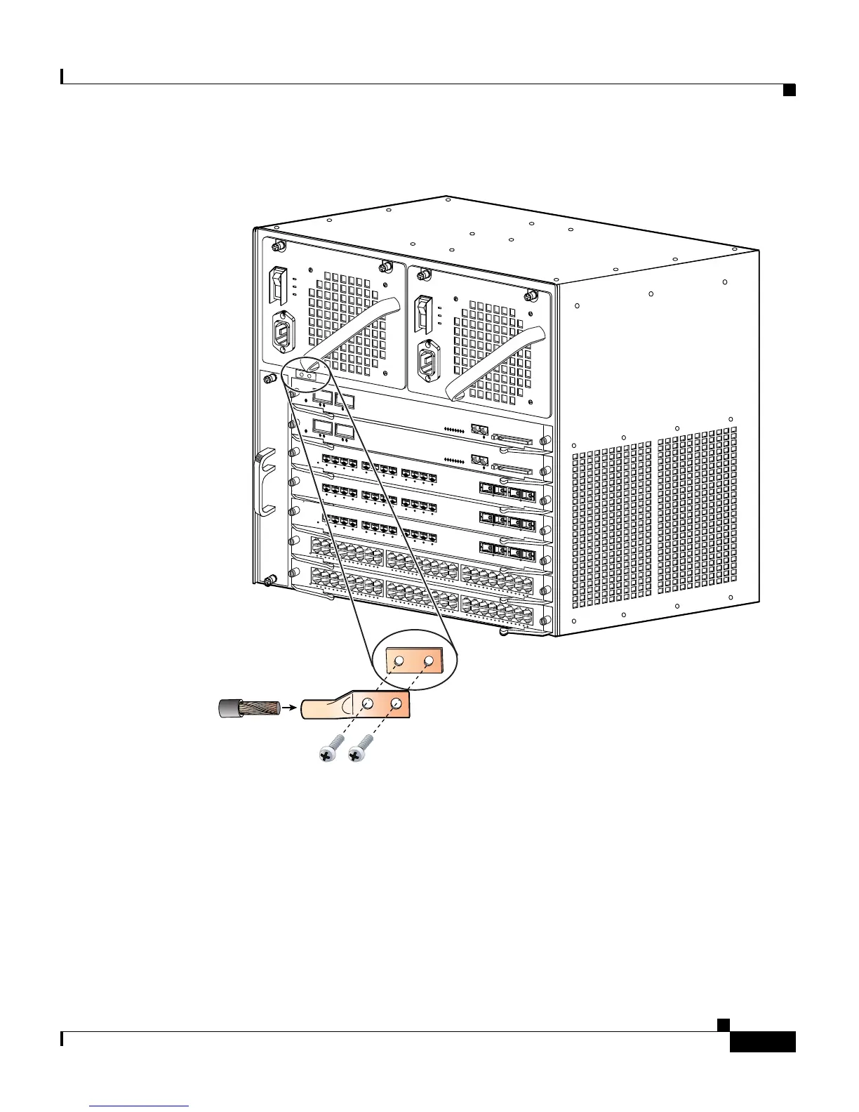
Figure 3-17 Connecting System Ground on the Switch
Step 5 Remove the label that covers the grounding pad.
Step 6 Place the grounding lug against the grounding pad, aligning the holes. Insert the
two M4 screws through the holes in the grounding lug and grounding pad
(
Figure 3-15 and Figure 3-17).
Ensure that the grounding lug and the attached wire will not interfere with other
switch hardware or rack equipment.
79482
WS-X4448-GB-RJ45
STATUS
12
11
10
9
8
7
6
5
4
3
2
1
14
13
16
15
28
27
26
25
24
23
22
21
20
19
18
17
30
29
32
31
44
43
42
41
40
39
38
37
36
35
34
33
46
45
48
47
10/1
00B
ASE
-T
X
ET
HER
N
ET
M
UL
T
I-SP
EED
G
IG
AB
IT
E
TH
E
R
NET
S
W
IT
CHI
NG
MO
D
ULE
WS-X4448-GB-RJ45
STATUS
12
11
10
9
8
7
6
5
4
3
2
1
14
13
16
15
28
27
26
25
24
23
22
21
20
19
18
17
30
29
32
31
44
43
42
41
40
39
38
37
36
35
34
33
46
45
48
47
1
0/1
00
B
ASE
-T
X
ETH
ER
NE
T
M
U
LTI-S
P
EE
D
G
IG
AB
IT E
THE
RNE
T
S
W
IT
CHING
M
O
D
ULE
1
STAT
US
W
S-X4412-2G
B-TX
2
3
4
5
6
7
8
9
10
11
12
17
1
S
TA
TU
S
W
S-X4412-2
GB-TX
2
3
4
5
6
7
8
9
10
11
12
17
1
STA
TU
S
W
S
-X
4412-2
GB
-T
X
2
3
4
5
6
7
8
9
1
0
11
12
17
UPLIN
K
UPLINK
CONSOLE
10/100
BASE-TX
STATUS
UPLINK
UPLINK
CONSOLE
10/100
BASE-TX
STATUS
Grounding
pad
Grounding lug
Wire
Screws (M4)

 Loading...


